
TM 5-3805-281-24-2
Frames
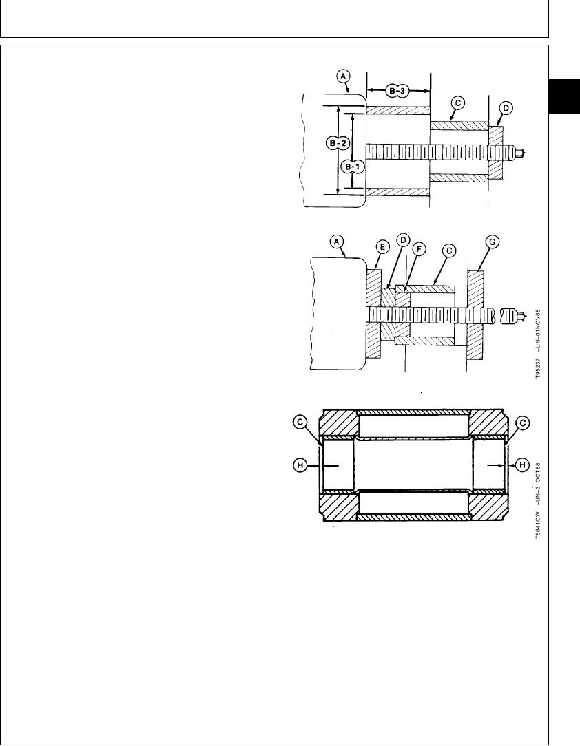
REMOVE AND INSTALL BUSHINGS AND
SEALS
33
3340
NOTE: Bushing can also be removed by welding three to
19
five weld beads on the inside of bushing. Bushing
will shrink enough to permit removal using a
hammer.
1. Remove and install bushings (C) and dust seals using
bushing, bearing, and seal driver set.
2. Install bushings with lubrication hole aligned with
lubrication passage in pivot.
3. Install bushing to a depth equal to thickness of dust
seal (H).
4. Install dust seals with lip toward outside of component.
A--Hydraulic Ram
B1--Pipe--Minimum ID to Clear Bushing OD
B2--Pipe--Maximum OD
B3--Pipe--Length of Bushing
C--Bushing
D--Disk
E--Bushing Stop (Disk)
F--Pilot (Disk)
G--Ram Stop (Disk)
H--Thickness of Dust Seal
TX,33,GG2320
1925NOV961/1