
TM 5-3805-281-24-2
Hydraulic System
CAUTION: To avoid injury from escaping fluid
under pressure, stop engine and relieve the
33
pressure in the system before disconnecting
3360
hydraulic or other lines. Tighten all connections
21
before applying pressure.
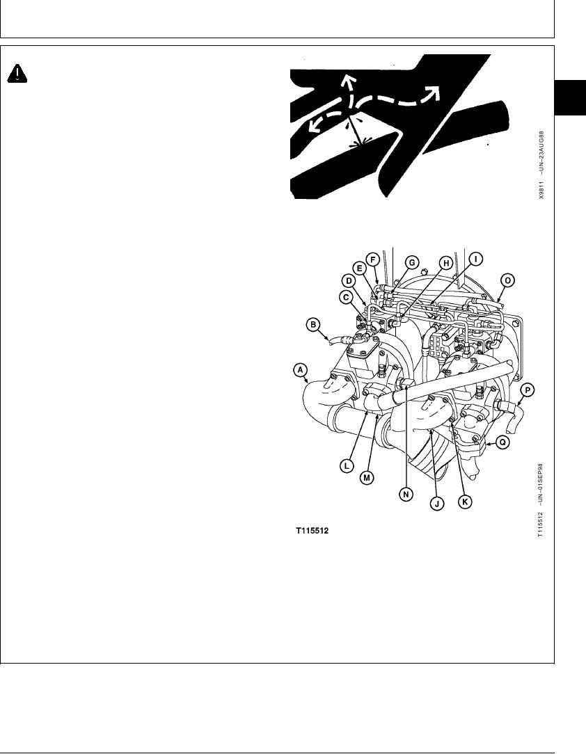
4. Disconnect lines (B, C, E--H, L and N).
Disconnect wiring harness connector from pump
pressure sensor (M).
5. Remove cap screws (K) and elbows (A and J).
A--Rear Pump Inlet Port-to-Hydraulic Oil Tank Elbow
B--Rear Pump Regulator Speed Sense Signal
Port-to-Speed Solenoid Valve
C--Rear Pump Regulator Speed Sense Signal
Port-to-Front Pump Regulator Speed Sense Signal
Port
D--Air Bleed Plug
E--Rear Pump Regulator Top Port-to-Front Pump
Regulator Side Port
F--Rear Pump Regulator No. 2 Port-to-Rear Pump
Control Valve in Left Control Valve
G--Rear Pump Regulator E (Inlet) Port-to-Pilot Pump
Outlet
H--Rear Pump Regulator Side Port-to-Front Pump
Regulator Top Port
I--Cap Screw (4 used)
J--Front Pump Inlet Port-to-Hydraulic Oil Tank Elbow
K--Cap Screw (8 used)
L--Rear Pump Discharge Port-to-Left Control Valve
M--Pump Pressure Sensor (2 used)
N--Rear Pump Attenuator Line
O--Front Pump Regulator No. 2 Port-to-Front Pump
Control Valve in Right Control Valve
P--Front Pump Attenuator Line
Q--Front Pump Discharge Port-to-Right Left Control
Valve
Continued on next page
CED,OUOE027,295
1903JUN982/3
19-61