
TM 5-3805-281-24-2
Hydraulic System
2. Turn upperstructure 90 to tracks.
33
3. Remove bottom cover under rear of cab.
3360
59
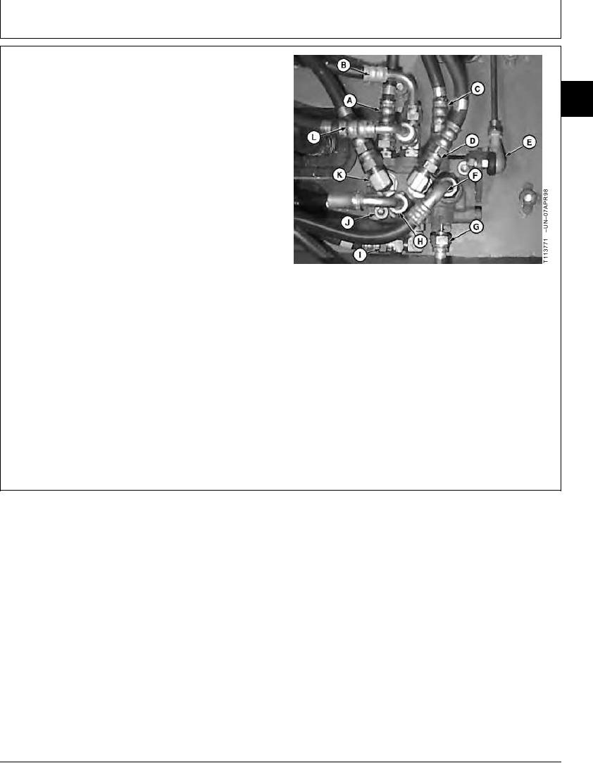
4. Disconnect pilot shut-off valve linkage (E).
5. Mark lines to aid assembly.
6. Disconnect lines (A--D, F--I, K and L).
7. Remove cap screws (J) to remove pilot shut-off valve.
8. Repair or replace valve as necessary.
9. Install valve. Tighten cap screws.
Head-to-Support Pilot Shut-Off Valve Cap Screw--Specification
A--To Right Pilot Controller P Port
Torque ............................................................................. 49 Nm (36 lb-ft)
B--To Propel Pilot Controller P Port
C--To Left Pilot Controller P Port
10. Connect lines.
D--From Left Pilot Controller T Port
E--Pilot Shut-Off Valve Linkage
11. Connect linkage. Check pilot shut-off valve linkage
F--To Flow Regulator Valve
G--From Pilot Pressure Regulating Valve
adjustment. (See procedure in this group.)
H--From Propel Pilot Controller T Port
I--To Solenoid Valve Manifold DD Port
J--Cap Screw (2 used)
K--From Right Pilot Controller T Port
L--To Solenoid Valve Manifold PF Port
CED,OUOE027,307
1905JUN982/2
19-95