
TM 5-3805-281-24-2
Hydraulic System
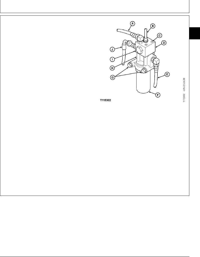
2. Disconnect lines (A, B, E and J).
33
3. Remove cap screws and lock washers (G) to remove
3360
pilot pressure regulating valve and pilot filter.
57
4. Replace parts as necessary.
5. Install new pilot filter element.
Tighten filter element housing.
Pilot Filter Element Housing-to-Filter Head--Specification
Torque .......................................................................... 25 Nm (220 lb-in.)
6. Tighten cap screws (C).
Regulating Valve Housing-to-Filter Head Cap Screw--Specification
Torque .......................................................................... 20 Nm (175 lb-in.)
7. Tighten cap screws (G).
A--From Pilot Pressure Regulating Valve Top
Front Port-to-Hydraulic Oil Tank Return
Filter Head-to-Support Cap Screw--Specification
Manifold Line
B--From Pilot Pressure Regulating Valve Top
Torque ............................................................................. 49 Nm (36 lb-ft)
Rear Port-to-System Relief Valve Manifold
Block
8. Connect lines.
C--Cap Screw (4 used)
D--Pilot Pressure Regulating Valve Housing
E--From Filter Head Left Side Port-to-Pilot Pump
9. Do Pilot Pressure Regulating Valve Test and
Line
Adjustment to check pressure setting. (See procedure
F--Pilot Filter
in Group 9025-25.)
G--Cap Screw and Lock Washer (2 used)
H--Filter Head
I--Plug
J--From Filter Head Right Side Port-to-Pilot
Shut-Off Valve Line
CED,OUOE027,305
1905JUN982/2
19-93