
TM 5-3805-281-24-2
Hydraulic Impact Breaker
33
1--O-Ring
11--O-Ring
22--Spacer Barrel
33--Plug 1/4" Gas
3
2--Shell Fixing Screw
12--Mushroom Valve
23--O-Ring
34--Sealing Washer
3--Half Lower Shell - Spy
13--Box Body Cover
24--Plug
35--Screw
Hole
14--Dowel
25--O-Ring
36--Seeger (Snap Ring)
4--Diaphragm
15--O-Ring
26--Barrel
37--H.P. Connection 1 in.
5--Half Upper Shell
16--Distributor Box Body
27--Slide
38--L.P. Connection 1-1/4
6--Inflating Screw
17--Distributor
28--Spring
in.
7--Sealing Ring
18--Valve Body
29--Adjustment Shim
39--Washer
8--Accumulator Screw
19--Needle
30--O-Ring
40--O-Ring
9--Side Bolt-Rubber Type
20--Spring
31--Guiding Plug
10--Head
21--Adjustment Shim
32--Link
CED,OUOE039,1 1920MAR992/42
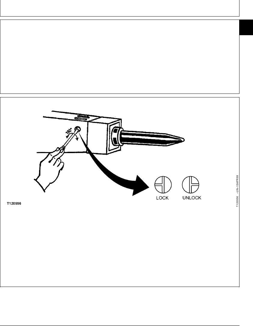
2. In order to remove tool, insure that retaining axles
DISASSEMBLE TOOL, CAP, CONNECTORS AND
are not in locked position.
SHOCK ABSORBERS
3. With large screwdriver, push in on locking bolt and
1. Position breaker horizontally on a flat surface, using
rotate to unlocked position.
a suitable lifting device.
Continued on next page
CED,OUOE039,1 1920MAR993/42
20-2