
TM 5-3805-281-24-2
Hydraulic Impact Breaker
33
CAUTION: The approximate weight of the
7
breaker is 905 kg (1994 lb).
NOTE: Before removing side shock absorbers, mark
support plate and frame, to identify correct
position.
12. Remove both side shock absorbers by removing 8
bolts and washers from each.
13. Slide breaker out of case, as shown. Use appropriate
hook.
CED,OUOE039,1 1920MAR9910/42
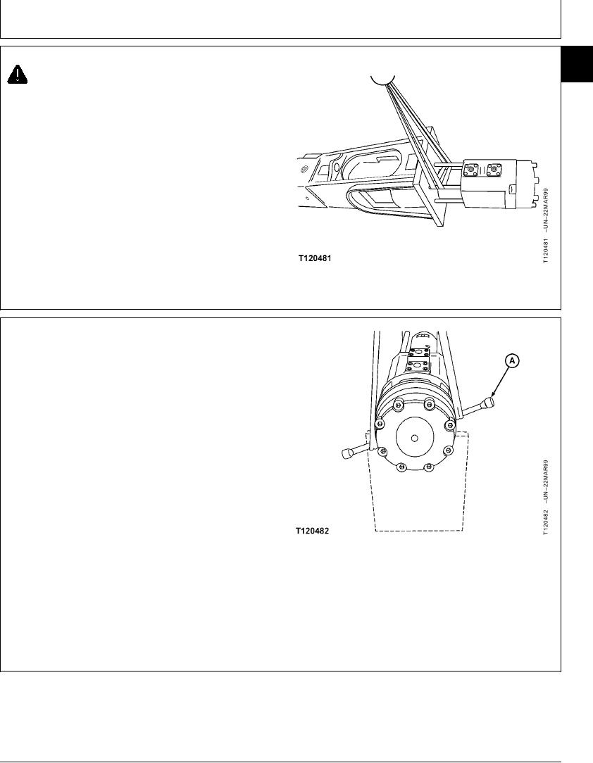
14. Once the breaker is out of the case, install two bolts
(A) into the head assembly. If necessary, these bolts
can be removed from the accumulator.
NOTE: Be certain to check the condition of the
accumulator bolts by holding the bolt by the
thread end and tapping the head with a hammer.
The bolt should ring.
15. Install breaker in suitable holding bracket to keep in
upright position.
A--Bolt
Continued on next page
CED,OUOE039,1 1920MAR9911/42
20-6