
TM 5-3805-281-24-2
Hydraulic Impact Breaker
33
6. With two wrenches, remove 12 nuts, bolts and
5
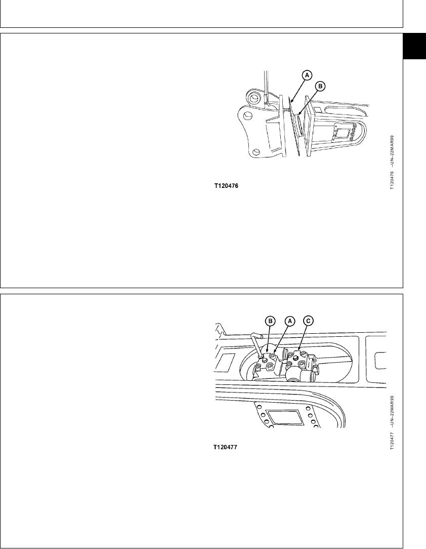
7. Remove top shock absorber holder (A) and the upper
shock absorber (B).
A--Shock Absorber Holder
B--Upper Shock Absorber
CED,OUOE039,1 1920MAR996/42
8. With an Allen wrench, remove screws (A) holding high
pressure link group (B) and check condition of O-ring.
9. Repeat preceding step for the Low Pressure Link
group (C), located directly below High Pressure group.
A--Screw (8 used)
B--High Pressure Link
C--Low Pressure Link
Continued on next page
CED,OUOE039,1 1920MAR997/42
20-4