TM 5-3805-294-10
OPERATOR MAINTENANCE
DESCRIPTION AND USE OF OPERATOR CONTROLS AND INDICATORS
INTRODUCTION
The following tables and illustrations provide the description and use of the controls and indicators pertaining to the
front switch panel, heater and air conditioner control panel, control pedals and levers, left console, left and right
control levers, seat controls and arm rest, coolant heater and cab door, and warning indicators and alarms.
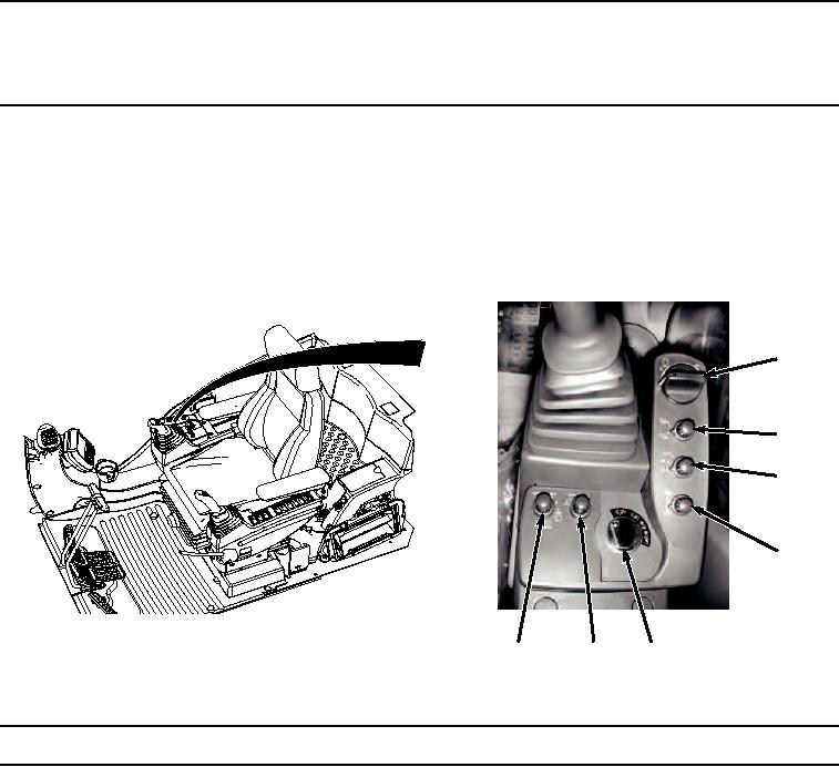
Table 1.
Front Switch Panel.
3
4
5
6
1
2
7
HYEX00867
Figure 1. Front Switch Panel.
Key
Control/Indicator
Function
1
Washer/Wiper
Wiper switch has several positions. The OFF position stops the wipers from
Switch
operating and parks them. The INT position operates the wipers intermittently
at the interval selected by the switch position. The ON position operates the
wipers continuously. To operate the washer, push and hold switch down for no
more than 20 seconds. Note that the wiper will not operate unless the
windshield is completely closed.
2
Operating Lights
This is a three-position switch. The first position turns on the drive light. Front
Switch
Switch panel will also illuminate. The second position turns on the boom work
lights, the front cab work lights, and the drive light. If the default screen on the
monitor is displayed, the background goes from white to black.

