
TM 5-3805-294-10
0025
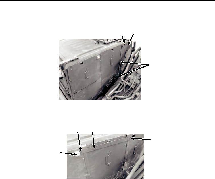
RIGHT SIDE CAB INSTALLATION - Continued
3.
Position cover (Figure 3, Item 7) on cab hook (Figure 3, Item 8) and behind brackets (Figure 3, Item 9).
8
7
9
HYEX01550
Figure 3. Right Side Front Cover Installation.
4.
Position plate (Figure 4, Item 10) over tabs (Figure 4, Item 11) and turn lock (Figure 4, Item 12) to lock in place.
11
10
11
12
HYEX01551
Figure 4. Lock Bar Installation.
END OF TASK
LEFT SIDE CAB INSTALLATION
1.
Position cover (Figure 5, Item 13) over door hook (Figure 5, Item 14) and behind brackets (Figure 5, Item 15).