
TM 5-2420-230-24-1
Table 3-6. Unit Troubleshooting Table. -- Continued
Malfunction
Test or Inspection
Corrective Action
32.
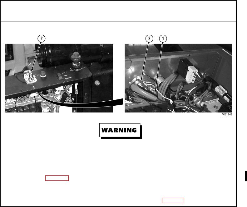
NO POWER AT IGNITION SWITCH.
Remove all jewelry such as rings, dog tags, bracelets, etc. If jewelry or tools contact positive electrical circuits, a
direct short may result. Damage to equipment and injury or death to personnel may occur.
Step 1.
Check for 24 Vdc on wire 24 (1) at ignition switch (2) (refer to FO-3).
If 24 Vdc is not present on wire 24 (1), check wire for continuity. Replace wire as necessary
Step 2.
With ignition switch in IGN position, check for 24 Vdc on wire 7 (3) at ignition switch (2) (refer to FO-3).
If 24 Vdc is not present on wire 7 (3), replace ignition switch (Para 12-18).
Change 1