
TM 5-2420-230-24-1
Maintenance & Service Manual
R & HR32000 3 & 6 Speed LD
Figure 90
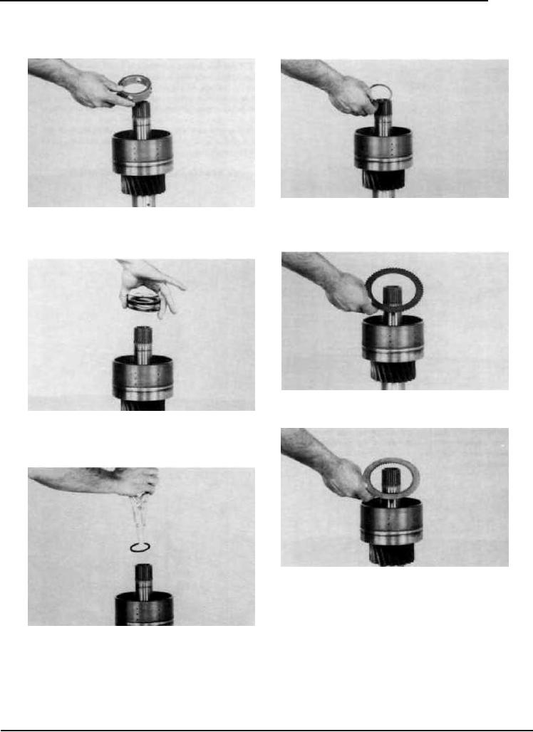
Position ring retainer over retainer ring.
Figure 87
Install piston spacer.
Figure 91
Install one steel disc.
Figure 88
See NOTE in figure 83. Install disc springs. First spring with
large diameter toward spacer. Alternate (5) five washers. See
page 59, Figure C.
Figure 92
Install one friction disc. NOTE: The friction discs in the
low clutch has a higher co-efficient rating than the friction
discs in the other clutches, therefore the discs must not
be mixed. The low clutch inner disc can be identified by
an "X" stamped on one side of the inner teeth. The low
clutch inner disc also has a strip of non-solube yellow
paint sprayed on the outer edge of the disc.Alternate steel
Figure 89
and friction discs until the proper amount of discs are installed.
Position return spring retainer ring on clutch shaft. Compress
First disc next to the piston is steel, last disc installed is friction.
disc springs and install retainer ring.
--16--
F-61