
TM 5-2420-230-24-1
Maintenance & Service Manual
R & HR32000 3 & 6 Speed LD
NOTE: Each disc spring assembly is made up of selected
springs to precisely match each part within this assembly.
Failure to replace all piston return springs can result in
unequal deflection within the spring pack. The result of
this imbalance may adversely affect overall life of springs.
The disc spring packs are to be used as complete assem-
blies and care should be taken not to intermix the individ-
ual disc springs with disc springs in another clutch or disc
spring pack.
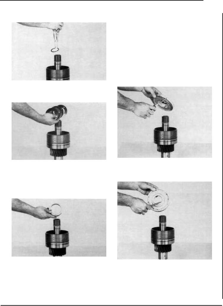
1ST SPEED CLUTCH REASSEMBLY
Figure 82
Remove return disc spring retainer ring.
Figure 85
Figure 83
Install clutch piston outer seal ring.
Remove piston return disc spring. NOTE: Disc springs in
the low clutch are different than springs in the forward and
reverse clutch. Do not mix low clutch springs with for-
ward and reverse springs (see note at top of page). Non
modulated units will have return springs in forward &
reverse clutches.
Figure 84
Figure 86
Remove return spring to piston spacer. Turn clutch over and tap
Install clutch piston inner seal ring. Install piston into clutch
clutch shaft on a block of wood to remove clutch piston.
drum. Use caution as not to damage seal rings.
See cleaning and inspection page.
--15--