TM 5-2420-230-24-1
Spicer Speciality Axle Division - Technical Publications
SECTION 1
PREPARATION FOR OVERHAUL
1.1
Before attempting to remove road wheels, drive vehicle onto a solid concrete base and over a
maintenance pit if possible, preferably after a short run to warm the oil.
1.2
Chock appropriate wheels.
1.3
With road wheels on ground, loosen wheel nuts on both sides.
1.4
Raise axle and support with suitable axle stands.
1.5
Remove wheel nuts and take off road wheels.
1.6
With suitable drip tray placed under drive head (approx. capacity drive head 17 pints (9.7 litres) and hub
2 pints (1.15 litres).
Remove all drain and filler plugs to drain oil.
1.7
Disconnect propshaft from drive head.
SECTION 2
REMOVAL OF COMPLETE DRIVE HEAD ASSEMBLY
2.1
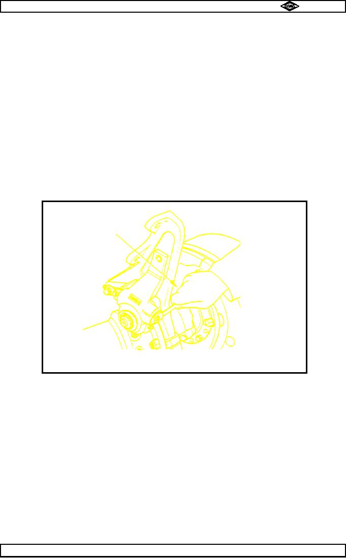
Engage main diff lock, then remove brake drum retaining setscrew (84 - H82) then back off brake
adjustment by turning hexagonal adjuster screw on slack adjuster (49- H82) in an anti-clockwise
direction (see fig. no.1).
TP31
Turn adjuster
anti-clockwise
Fig. No.1
Support brake drum (2 - H82) (approx. weight - 105 lbs.) then insert 2 off 7/16" UNF x 11/2" long extractor
2.2
bolts into tapped holes provided in brake drum and tighten evenly to draw drum from hub flange
(20 - H82).
Clean inside of brake drum with a clean damp cloth (do not use paraffin).
2.3
Remove planet carrier setscrews with washers (82 & 81 - H82) then insert 2 off 7/16" UNF extractor bolts
2.4
into holes in planet carrier flange (79 - H82) and tighten evenly to pull planet carrier assembly from hub
(20 - H82).
2.5
Pull out drive shaft / sun gear assembly from hub (20 - H77).
2.6
Repeat operations 2.1 to 2.5 for other hub end.
2.7
Disengage main diff. lock.
2.8
Remove axle casing nuts (33) and their washers (34).
Scribe a line on diff. flange o/dia and axle casing to aid re-assembly.
Support drive head with a sling and fit 2 off 7/16 "UNF x 1 1/2 " long extractor bolts into tapped holes
2.9
provided in axle flange and tighten evenly to draw drive head from axle casing (52).
2.10
Remove any sealant from axle casing and gear casing mounting faces (52 & 19) using a suitable
sealant remover such as Loctite Chisel Gasket Remover or by carefully scraping sealant from faces.
Manual No. 1785 Issue A
Page No.E3
Spicer Speciality Axle Division
J-113

