
TM 5-2420-230-24-1
Spicer Speciality Axle Division - Technical Publications
SECTION 8
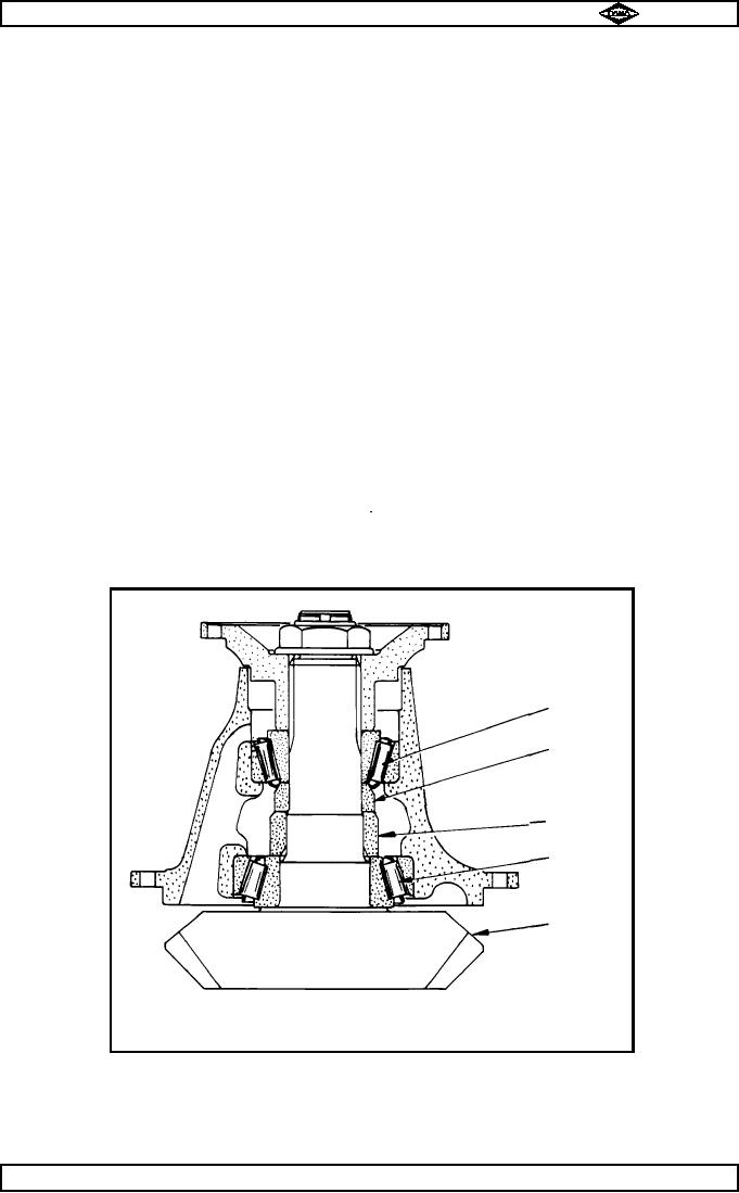
SPIRAL BEVEL PINION SUB ASSEMBLY - SEE FIG. No. 2
8.1
Fit inner and outer bearing cups (31 & 25) into their respective bores in bearing housing (22).
8.2
Press inner bearing cone (31A) onto pinion shaft (32).
8.3
Pinion assembly as follows :-
Fit inner bearing spacer (30) large inside chamfer end first, then outer spacer (29) large outside chamfer
outwards onto pinion shaft (32). Feed assembly into position in housing.
Note :-
If new parts are being fitted, then assemble with largest of available spacers.
This is to ensure that bearing pre-load is erred on low side, thus preventing too great a
pre-load and resultant bearing damage.
8.4
Press outer bearing cone (25A) into position on pinion.
8.5
Press coupling flange (27) onto pinion splines and secure with nut (28).
8.6
Place assembly in vice (clamp on holding plate fitted to coupling flange).
8.7
Progressively tighten nut (28) whilst rotating and shock loading bearing housing (22) with a rawhide
mallet, to torque setting of 800 - 900 lbs. ft. (1085 - 1220 Nm).
8.8
Remove assembly from vice, take off holding plate.
TP72
Outer bearing
Outer spacer
Inner spacer
Inner bearing
Pinion
Fig No. 2
Manual No. 1785 Issue A
Page No.E7
Spicer Speciality Axle Division
J-117