
TM 5-2420-230-24-1
Spicer Speciality Axle Division - Technical Publications
SECTION 13
FITTING SPIRAL BEVEL WHEEL (CROWNWHEEL) AND DIFFERENTIAL INTO
BEVEL CASING
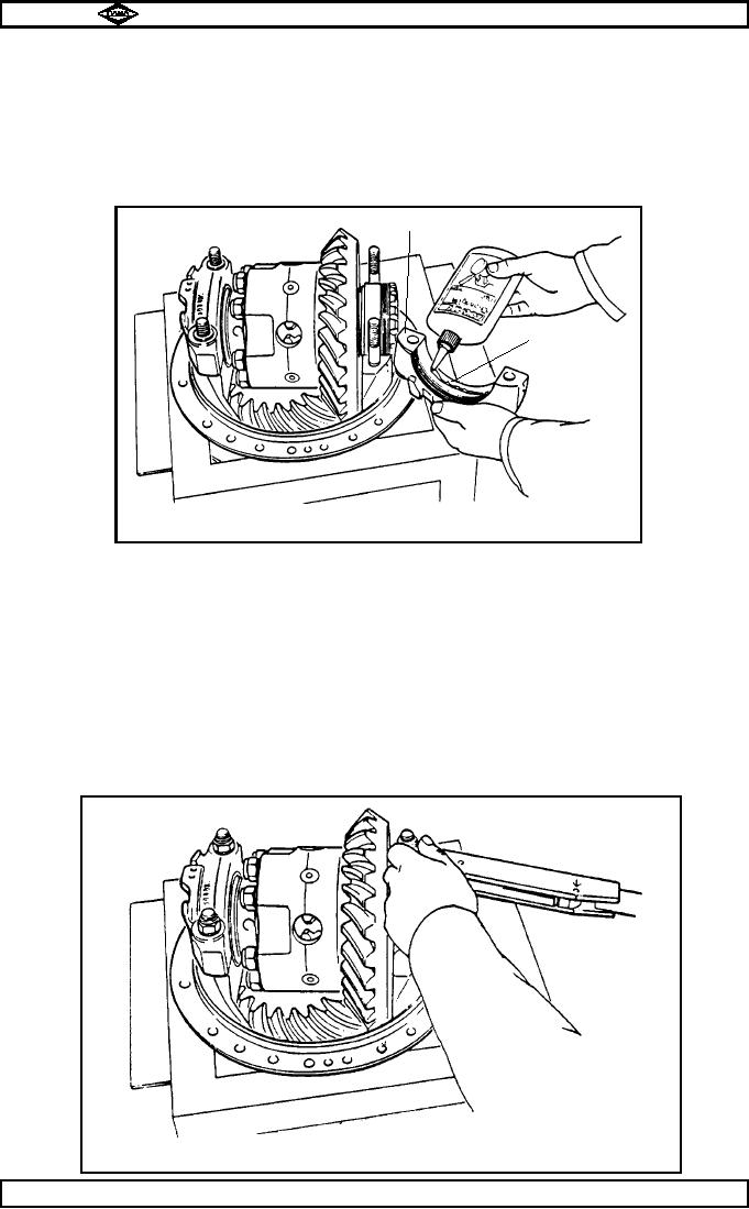
Apply a thin bead of ' Loctite 641 ', using correct applicator to give a 1/8 " wide band, into bevel casing
13.1
strap bores (12). See fig. no. 6.
This is to prevent possibility of diff. bearing cups (13 & 45) spinning in service.
Note :-
Assembly and setting procedures are to be completed immediately so as to avoid the
' Loctite ' hardening, and preventing adjustment of bearing cups (14 & 44).
TP17
Bevel casing strap (12)
●
1/8" wide band
'Loctite 641'
●
Fig No.6
13.2
Hold diff. bearing cups (14 & 44) in position on diff. bearing cones (14A & 44A) and place spiral bevel
wheel (crownwheel) and differential assembly in position in bevel casing (19).
13.3
Fit diff. bearing adjusting nuts (13 & 45) onto half threads of bevel casing legs (19).
Recheck freedom of nuts in threads.
13.4
Refit bevel casing straps (12) (by hand) onto bevel casing strap studs (18) to locate on bearing
cups (14 & 44) and adjusting nuts (13 & 45).
Note :-
Ensuring all matching marks coincide to obviate misalignment of straps (12).
13.5
Turn bearing adjusting nuts (13 & 45) hand tight against bearings (14 / 14A & 44 / 44A).
13.6
Fit bevel casing strap washers and bevel casing strap stud nuts (11 & 10), then tighten nuts to
128 - 142 lbs ft. (174 - 193Nm.). See fig. no.7.
TP18
Fig. No.7
Page No.E12
Manual No. 1785 Issue A
Spicer Speciality Axle Division
J-122