
TM 5-2420-230-24-1
Spicer Speciality Axle Division - Technical Publications
SECTION 14
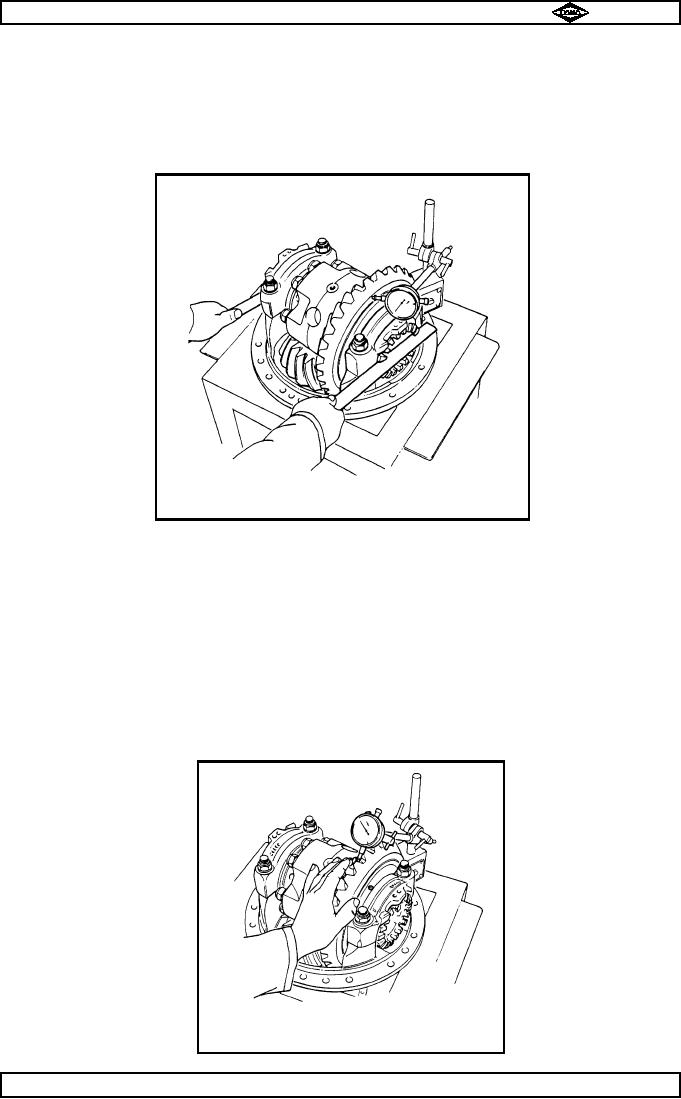
SETTING " NO END FLOAT " CONDITION
14.1
Set up a dial indicator on back face of spiral bevel wheel (crownwheel) (43) as shown in fig. 8. and
screw in each diff. bearing adjusting nut (13 & 45) just sufficiently to ensure no spiral bevel wheel
(crownwheel) axial movement is registered on dial indicator.
14.2
Tap bevel casing straps (12) and rotate bevel wheel (crownwheel) then check that no axial movement is
present.
TP19
Fig No. 8
SECTION 15
SETTING THE SPIRAL BEVEL WHEEL (CROWNWHEEL) AND PINION BACKLASH
15.1
Move dial indicator onto spiral bevel wheel (crownwheel) tooth (43) as shown in fig no.9. Hold spiral
bevel pinion (32) still and rock spiral bevel wheel (crownwheel) (43) backwards and forwards, to check
free play between gears (backlash), and note variation of indicator reading.
Repeat above operation three more times so that four readings are taken at various positions equally
15.2
spaced around spiral bevel wheel (crownwheel) (43). Variations of readings on dial indicator must be
within limits of 0.008 " to 0.013 " (0.203 to 0.330mm). If difference in backlash of more than half
backlash tolerance exists between any tooth mesh positions, then assembly should be further examined
for cause and rectified.
TP20
Fig No. 9
Manual No. 1785 Issue A
Page No.E13
Spicer Speciality Axle Division
J-123