
TM 5-2420-230-24-1
Spicer Speciality Axle Division - Technical Publications
SECTION 19
REFITTING DRIVE HEAD INTO AXLE
19.1
Refit axle casing studs (8), tightening to procedure shown on page D23.
19.2
Apply a thin film of Loctite no. 515 Liquid Gasket to axle casing mating face on bevel casing (22).
19.3
With drive head supported with a suitable sling offer assembly to axle casing and tap into position using
a hide faced hammer.
19.4
Fit axle casing washers (34) and nuts (33) then tighten nuts to 99 - 109lbs. ft. (134 - 148Nm).
19.5
Fit hubs as follows :-
a)
Slide drive shaft (57 - H82) fully home in hub until splines can be felt to engage fully with
differential gears.
b)
Slide planet carrier / hub cap assembly into position ensuring gears mesh correctly, then
fit planet carrier setscrews with washers (82 & 81- H82), tightening to
110 - 125lbs.ft. (149 - 169Nm.).
c)
Repeat operations a) and b) for other hub.
19.6
Fit air chamber (54) onto mounting plate and secure into position with locknuts (56) and washers (55).
Note :-
If new air chamber (54) is to be used, the push rod needs to be cut, prior to fitting, to
same length as on original air chamber. This is because air chamber manufacturer
supplies chambers with push rods to suit all applications.
When fitting diff. lock air chambers ensure that air chamber push rod is fitted in line
and operates at 90 to mounting bracket.
This is to ensure smooth operation and avoid jamming up problems in service.
19.7
Assemble locknut (59) and yoke (58) onto push rod end.
19.8
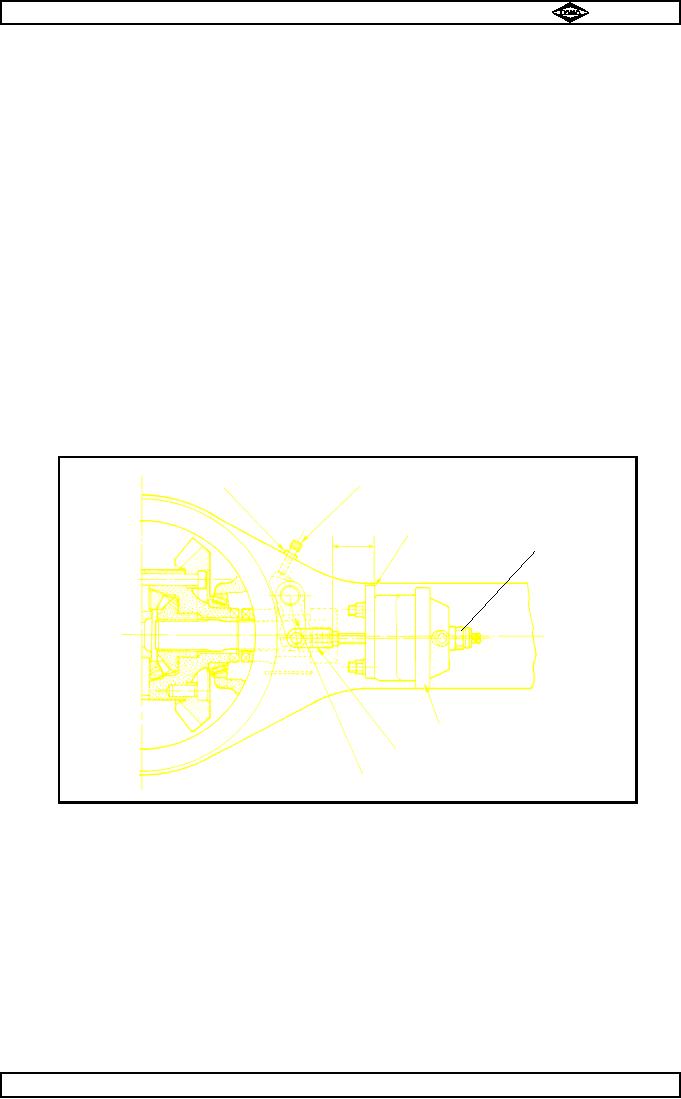
Screw yoke onto push rod until distance from air chamber mounting face to push rod is
9mm - see fig. no.12.
TP76
Item 7
Item 6
Mounting face
9mm
Item 53
Item 54
Item 58
Item 1
Fig. No.12
19.9
Secure yoke (58) with locknut (59).
19.10
Connect diff. lock switch (53), if fitted, and air supply to air chamber (54).
19.11
Check air chamber to yoke distance with air in system.
SECTION 20
DIFF LOCK SETTING PROCEDURE.
20.1
Engage diff. lock then check that lock is fully engaged by rotating one hub, if lock is engaged, other hub
will rotate in same direction.
20.2
Assemble stop screw (6) and locknut (7) together then apply Hylomar sealant to setscrew threads prior
to fitting into axle casing (52).
20.3
Screw stop screw into casing (52) until contact with operating lever is felt.
20.3
Disengage diff. lock.
Give stop screw (6) one half turn clockwise, then lock in position with locknut (7).
20.4
20.5
Check disengagement as follows :-
Rotate one hub and observe direction of other hub.
If lock is disengaged hubs will rotate in opposite directions.
Manual No. 1785 Issue A
Page No.E19
Spicer Speciality Axle Division
J-129