
TM 5-2420-230-24-1
Spicer Speciality Axle Division - Technical Publications
SECTION 22
FINAL ASSEMBLY / ADJUSTMENTS
22.1
Clean interfaces between Hub and brake drum then with brake drum (2 - H82) suitably supported, slide
into position on hub (20 - H82).
Note :-
Interfaces must be free from dirt , including liner material debris, rust and paint.
Failure to keep interfaces clean, can and will cause brake drum to distort upon
tightening of wheel nuts. For further details see BS AU50 : Part 2 : Section 7A : 1995.
TP1148
Clean interfaces
Clean interfaces
Fig.No.43
22.2
Fit brake drum retaining setscrew (84 - H82) and tighten to 72 - 80lbs. ft. (98 - 108Nm.).
22.3
Repeat operations 22.1 and 22.2 for other hub unit.
22.4
Re-connect prop shafts to coupling flange (27).
22.5
Refit drain plugs and refill axle with clean gear oil as stated in lubrication section at front of this manual.
Note :-
Always check final oil level at drive head. Oil flows freely through hubs and drive
head. When filling, top up each hub followed by drive head.
22.6
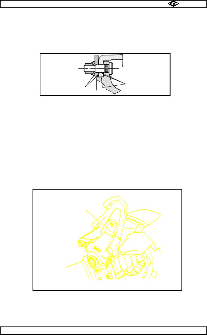
Adjust brakes as follows :-
a)
Turn adjusting screw on slack adjuster (49 - H82) clockwise until brake linings are hard
up against brake drum, then back off adjusting screw by 3/4of a turn as shown in
fig. no. 13.
b)
Check function of slack adjuster by performing a few brake applications.
TP31
Turn spanner clockwise
to adjust shoes
against brake drum.
Fig. No.13
22.7
Refit road wheels, securing with wheel nuts (1 - H82) and tighten nuts to
475 - 525lbs.ft. (644 - 712Nm.).
22.8
Remove axle supports, then lower vehicle to ground.
22.9
Remove chocks and lifting equipment.
Manual No. 1785 Issue A
Page No.E21
Spicer Speciality Axle Division
J-131