
TM 5-2420-230-24-1
WARNING
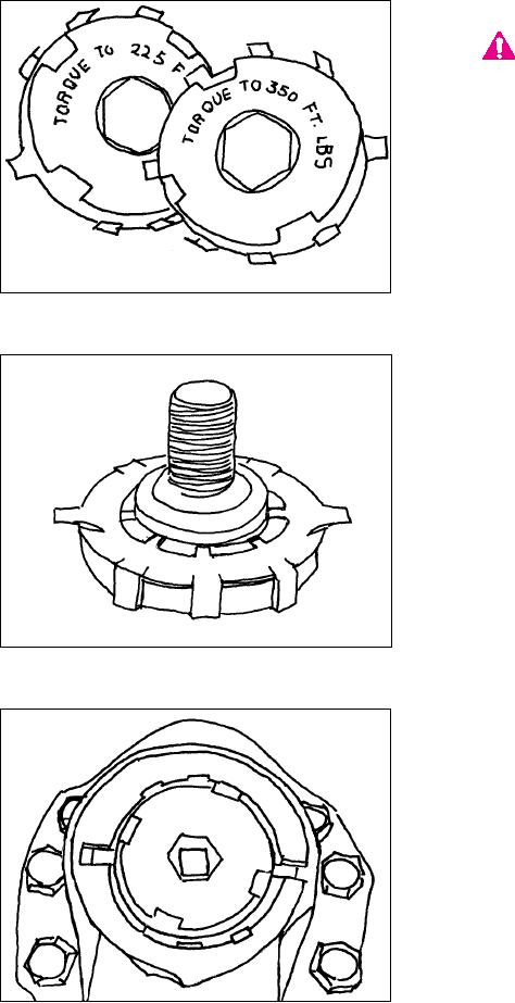
TAB LOCK RETAINERS ARE SUPPLIED
WITH THREE TORQUE SPECIFICA-
TIONS. EITHER 225 FT./LBS., 350
FT./LBS. OR 450 FT./LBS. THE TORQUE
V LUE IS STAMPED ON THE FACE
A
OF THE RETAINER. CHECK THE
TORQUE V LUE STAMPED ON YOUR
A
RETAINER
AND
THE
VEHICLE
MANUFAC-TURER'S SPECIFICATION TO
BE SURE YOUR RETAINER IS CORRECT!
(FIGURE 53).
Figure 53
4.
Apply the specified Never-Seize compound
in the threads of the sector shaft and retain-
er and on both sides of the friction washer
(Figure 54).
NOTE:
Do not apply Never-Seize compound to the
pitman arm contact side of the tab lock
washer.
Figure 54
5.
Screw the retainer into the output shaft by
hand. Align the tabs of the retainer in the
notches of the pitman arm (Figure 55).
Figure 55
K-59