
TM 5-2420-230-24-2
Section 0 - Engine Disassembly and Assembly - Group 00
Piston and Rod Assemblies - Installation (0-72)
B Series Shop Manual
Page 0-53
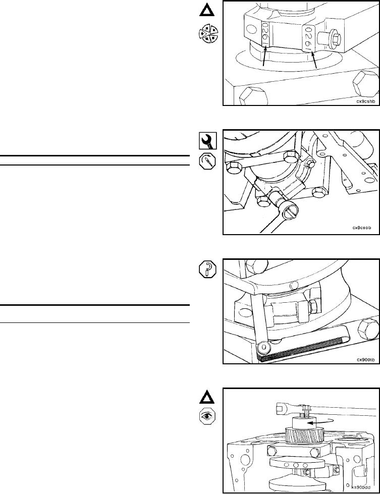
Caution: The four digit number stamped on the rod and
the cap at the parting line must match and be installed
on the oil cooler side of the engine.
Install the rod cap and capscrews to the connecting rod.
12 mm, Torque Wrench
Alternately, tighten the two capscrews
Step
Torque Value
1
35 Nm [26 ft-lb]
2
70 Nm [52 ft-lb]
3
100 Nm [74 ft-lb]
Measure the side clearance between the connecting rod
and crankshaft.
Do not measure the clearance between the rod cap
and crankshaft.
Side Clearance Limits
mm
in
0.10
MIN
0.004
0.30
MAX
0.012
Caution: The crankshaft must rotate freely.
Check for freedom of rotation as the rod caps are in-
stalled. If the crankshaft does not rotate freely, check the
installation of the rod bearings and the bearing size.
L-142