
TM 5-2420-230-24-2
Section 14 - Engine Testing - Group 14
Blowby Measurement
B Series Shop Manual
Page 14-7
Blowby Measurement
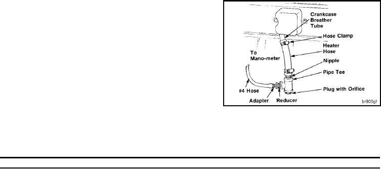
Blowby is generally recorded in liters/minute, but a water manometer may be used to measure blowby from the
breather tube after fabricating the following adaptation:
1. Plug the end of the straight portion of a pipe tee.
2. Drill an orifice in the plug (refer to the Blowby Con-
version Chart below for the appropriate orifice size).
3. Connect the open straight portion of the pipe tee to the
breather tube.
4. Connect a water manometer to the 90 degree outlet.
5. Use the Blowby Conversion Chart to convert the ma-
nometer reading to liters/minute.
Blowby Conversion Chart (5.613 mm [0.221 in] Orifice)
Inches of Water
Liters/Minute
Inches of Water
Liters/Minute
1
27
19
121
2
40
20
124
3
49
21
128
4
58
22
131
5
64
23
135
6
71
24
137
7
76
25
140
8
81
26
144
9
86
27
147
10
90
28
150
11
94
29
154
12
98
30
157
13
102
31
160
14
105
32
163
15
109
33
166
16
112
34
169
17
115
35
172
18
118
L-437