
TM 5-2420-230-24-2
Section 14 - Engine Testing - Group 14
Engine Dynamometer Test - Installation of the Engine (14-01)
B Series Shop Manual
Page 14-9
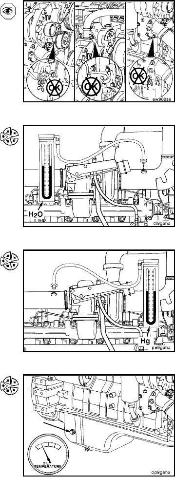
Inspect the engine for coolant leaks at connections, fit-
tings, plates, and plugs. Repair as necessary.
Connect a water manometer to the turbocharger air inlet
pipe to test air restriction.
NOTE: The manometer connection must be installed at a 90
degree angle to the air flow in a straight section of pipe, one
pipe diameter before the turbocharger.
NOTE: A vacuum gauge can be used in place of the water
manometer.
Minimum Gauge Capacity: 760 mm H20 [30 in. H20]
Connect a mercury manometer to a straight section of the
exhaust piping near the turbocharger outlet to check ex-
haust restriction.
NOTE: A pressure gauge can be used in place of the mer-
cury manometer.
NOTE: For automotive applications, a tapped hole is pro-
vided on the inlet side of the catalyst to check exhaust
restriction.
Minimum Gauge Capacity: 254 mm Hg. [10 in. Hg.]
Attach the lubricating oil temperature sensor in one of the
locations on the side of the engine as shown.
Minimum Gauge Capacity:
150C [300F]
L-439