
TM 5-2420-230-24-2
Section 14 - Engine Testing - Group 14
Engine Dynamometer Test - Installation of the Engine (14-01)
B Series Shop Manual
Page 14-13
Make sure the voltage supply matches that of the fuel
pump solenoid before connecting the electrical wires to
it.
Attach the throttle control rod onto the fuel pump throttle
lever.
ST-1273
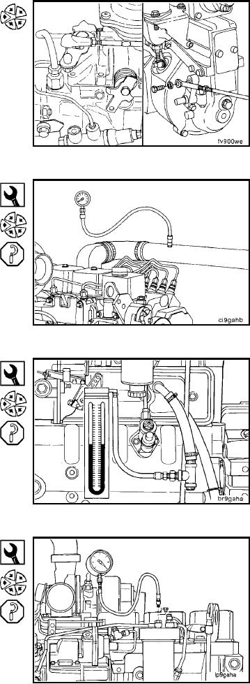
To determine the amount of turbocharger boost and
aftercooler/charge air cooler restriction install intake man-
ifold pressure gauges, Part No. ST-1273 in the turbo-
charger outlet and the intake manifold.
Part No. 3822676
For accurate engine crankcase blowby measurement, in-
sert a blowby checking tool in the crankcase breather
vent.
Connect a water manometer to the blowby tool Part No.
3822676. A pressure gauge can be used in place of the
manometer.
Minimum Gauge Capacity: 1270 mm H20 [50 in. H20]
Part No. ST-434
To measure fuel filter restriction, connect vacuum gauge,
Part No. ST-434, to the injection pump inlet line.
Minimum Gauge Capacity:
760 mm Hg [30 in. Hg]
L-443