
TM 5-2420-230-24-2
Engine Dynamometer Test - Installation of the Engine (14-01)
Section 14 - Engine Testing - Group 14
Page 14-8
B Series Shop Manual
Engine Dynamometer Test - Installa-
tion of the Engine (14-01)
Use engine lifting fixture, Part No. ST-125, to install the
engine to the test stand. Align and connect the dyna-
mometer. Refer to the manufacturer's instructions for
aligning and testing the engine.
NOTE: Make sure the dynamometer capacity is sufficient to
permit testing at 100 percent of the engine rated horsepower.
If the capacity is not enough, the testing procedure must be
modified to match the restrictions of the dynamometer.
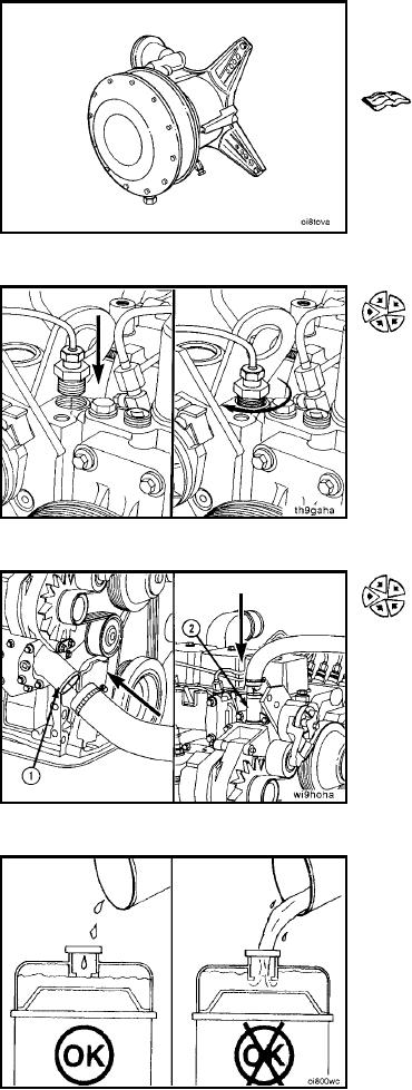
Install the coolant temperature sensor.
Minimum Gauge Capacity:
107C [225F]
Connect the coolant supply to the water inlet connection
(1).
Connect the coolant return to the water outlet connection
(2).
Install the drain plugs, close all the water drain cocks, and
make sure all the clamps and fittings are tight.
Connect the vent tube to the vent connection on the
thermostat housing.
Fill the cooling system with coolant to the bottom of the
fill neck in the radiator fill (or expansion) tank.
NOTE: Maximum Fill Rate is 14 Liters/min [3.5 U.S.
gallons/min]
L-438