
TM 5-2420-230-24-2
Connecting Rod (001-014)
B3.9 and B5.9 Series Engines
Page 1-40
Section 1 - Cylinder Block - Group 01
18 mm
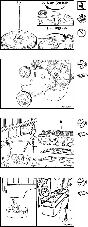
Install camshaft bolt and washer in 1991 engines equipped
with an in-line pump.
Torque Value: Step 1
27 Nm
[20 ft-lb]
2
Turn capscrew clockwise 180
degrees.
Install camshaft. Refer to Procedure 001-008.
Adjust the valve lash. Refer to Procedure 003-004.
Install gear cover. Refer to Procedure 001-031.
Install vibration damper. Refer to Procedure 001-052.
Install fan pulley. Refer to Procedure 008-039.
Connecting Rod (001-014)
Preparatory (001-014-000)
Drain the coolant. Refer to Procedure 008-018.
Remove the cylinder head. Refer to Procedure 002-004.
Drain the lubricating oil. Refer to Procedure 007-025.
Remove the lubricating oil pan and gasket. Refer to Pro-
cedure 007-025.
L-718