
TM 5-2420-230-24-2
B3.9 and B5.9 Series Engines
Connecting Rod (001-014)
Section 1 - Cylinder Block - Group 01
Page 1-43
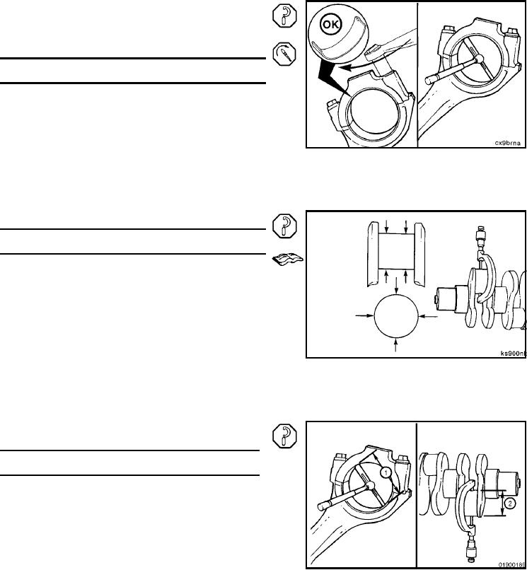
Measure the connecting rod crankshaft bore inside diam-
capscrews.
Torque Value: 100 Nm
[74 ft-lb]
Connecting Rod Bore Diameter (Bearings Installed)
mm
in
Standard
69.051
MIN
2.7185
69.103
MAX
2.7205
0.25 mm Oversize
68.801
MIN
2.7087
68.853
MAX
2.7107
0.50 mm Oversize
68.551
MIN
2.6989
68.603
MAX
2.7009
0.75 mm Oversize
68.301
MIN
2.6890
68.353
MAX
2.6911
1.00 mm Oversize
68.051
MIN
2.6792
68.103
MAX
2.6812
Measure the diameter of the rod journal on the crankshaft.
Crankshaft Rod Journal
Diameter
mm
in
Standard
68.962
MIN
2.7150
69.012
MAX
2.7170
0.25 mm Undersize
68.712
MIN
2.7052
68.762
MAX
2.7072
0.50 mm Undersize
68.462
MIN
2.6953
68.512
MAX
2.6973
0.75 mm Undersize
68.212
MIN
2.6855
68.262
MAX
2.6875
1.0 mm Undersize
67.952
MIN
2.6753
69.012
MAX
2.7170
NOTE: If crankshaft rod journals are not within the given
specifications, the crankshaft must be removed and
reground.
Bearing clearance equals rod inside diameter (with bear-
ing)(1) minus the crankshaft journal diameter (2).
Bearing Clearance
mm
in
0.038
MIN
0.0015
0.116
MAX
0.0046
L-721