
TM 5-2420-230-24-2
B3.9 and B5.9 Series Engines
Piston and Connecting Rod Assembly (001-054)
Section 1 - Cylinder Block - Group 01
Page 1-101
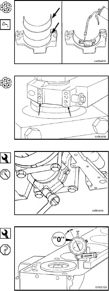
Install the bearing shell in the connecting rod cap with the
tang of the bearing in the slot to the cap.
Use clean lubricating engine oil to coat the inside diameter
of the connecting rod bearing shell.
The number stamped on the connecting rod and cap at the
parting line must match and be installed on the oil cooler
side of the engine.
Install the connecting rod cap and capscrews to the con-
necting rod.
12 mm
Tighten the two capscrews.
Torque Value: 35 Nm
[26 ft-lb]
Dial Indicator Assembly, Part No. 3823495
Use a fine-grit paper to remove any burrs from the cylinder
block head deck.
Zero the dial indicator to the cylinder block head deck.
L-779