
TM 5-2420-230-24-2
Piston and Connecting Rod Assembly (001-054)
B3.9 and B5.9 Series Engines
Page 1-106
Section 1 - Cylinder Block - Group 01
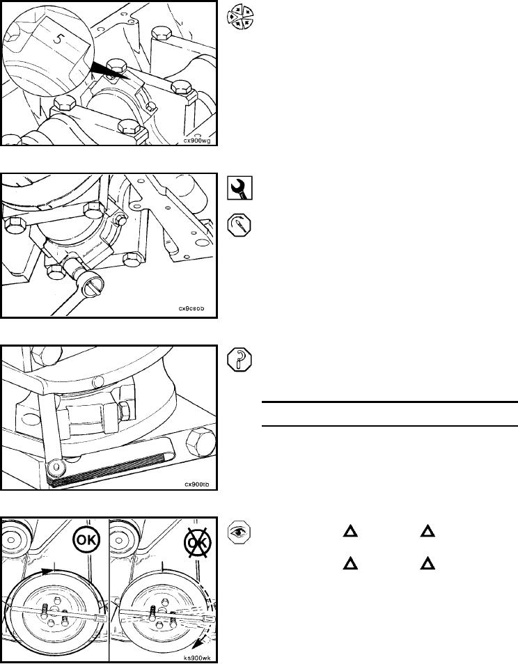
NOTE: The number stamped on the rod and cap at the
parting line must match and be installed on the oil cooler
side of the engine.
Install the connecting rod cap and capscrews to the con-
necting rod.
12 mm
Alternately, tighten the two capscrews.
Torque Value: Step 1
30 Nm
[22 ft-lb]
2
60 Nm
[44 ft-lb]
3
Turn 60 degrees clockwise.
NOTE: Do not measure the clearance between the rod cap
and crankshaft.
Measure the side clearance between the connecting rod
and crankshaft.
Side Clearance Limits
mm
in
0.10
MIN
0.004
0.33
MAX
0.013
CAUTION
The crankshaft must rotate freely.
CAUTION
If the connecting rod is not properly oriented (tang
opposite the camshaft), it will contact the camshaft and
lock the engine.
Check for freedom of rotation as the connecting rod caps
are installed. If the crankshaft does not rotate freely, check
the installation of the connecting rod bearings and the
bearing size.
L-784