
TM 5-2420-230-24-2
Piston and Connecting Rod Assembly (001-054)
B3.9 and B5.9 Series Engines
Page 1-102
Section 1 - Cylinder Block - Group 01
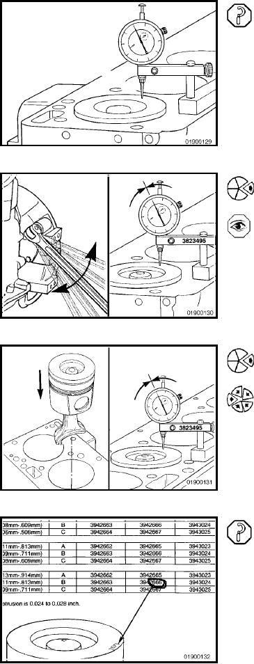
Move the dial indicator directly over the piston pin to elimi-
nate any side-to-side movement. Do not place the indicator
tip on the anodized area.
Rotate the crankshaft to top dead center (TDC). Rotate the
crankshaft clockwise and counterclockwise to find the
highest dial indicator reading.
Record the reading.
Remove the piston/connecting rod assembly from the No.
1 cylinder, and install the assembly into the No. 2 cylinder.
Repeat the procedure for every cylinder using the same
piston/connecting rod assembly.
The four digits on top of the piston are the last four digits
of the part number. Using the measured piston protrusion
and the grade of the piston that was measured, determine
the piston grade required to obtain protrusion of 0.610 to
0.711 mm [0.024 to 0.028 in].
L-780