
TM 5-2420-230-24-2
Tappet (004-015)
B3.9 and B5.9 Series Engines
Page 4-8
Section 4 - Cam Followers/Tappets - Group 04
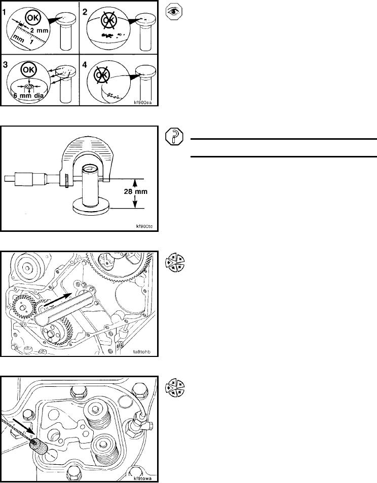
Pit marks on the tappet face are acceptable.
The following criteria defines the size of the pits allowed.
1. A single pit can not be greater than 2 mm [0.078 in].
2. Interconnection of pits is not allowed.
3. Total pits when added together should not exceed
6-mm [0.236-in] diameter or a total of 4 percent of the
tappet face.
4. No pitting is allowed on the edges of the wear face of
the tappet.
Measure the valve tappet stem.
Valve Tappet Stem Diameter
mm
in
15.936
MIN
0.627
15.977
MAX
0.629
Install (004-015-026)
Insert the plastic trough the full length of the cam bore.
Lower the tappet installation tool down the push tube hole,
through the tappet bore, and into the trough.
L-852