TM 5-2420-230-24-2
B3.9 and B5.9 Series Engines
Fuel Injection Pump, In-Line, Spill Port Timing (005-013)
Section 5 - Fuel System - Group 05
Page 5-37
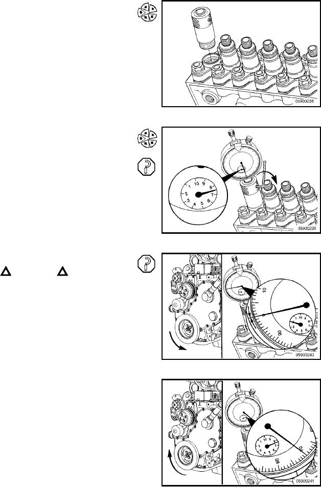
Step: 8
Install the dial indicator from the timing kit in place of the
No. 1 delivery valve holder and tighten finger-tight.
Step: 9
Loosen the set screw on the dial indicator adapter, and
install the dial indicator into the adapter. Position the dial
indicator to read between 7.0 and 9.0 mm, and lightly
tighten the set screw.
Overtightening the set screw will bind the dial indicator.
NOTE: The dial indicator is capable of measuring from 0 to
20.00 mm lift. The small inner dial is marked in increments
of 1.00 mm; the large outer dial is marked in increments of
0.01 mm. One revolution of the outer dial is equal to 1.00
mm. The inner dial only indicates 0 to 10.00 mm, but will
rotate twice as the indicator goes through the full range.
Step: 10
CAUTION
Be sure to disengage the timing pin before rotating the
crankshaft to avoid damage to the timing pin.
Use a barring tool to rotate the crankshaft in the direction
opposite normal direction of crankshaft rotation (counter-
clockwise from front of the engine) 1/4 turn or until the dial
indicator reading stops dropping. This is the inner base
circle of the fuel injection pump camshaft. Zero "0" the
indicator and note the reading on the small inner dial.
Step: 11
Rotate the crankshaft slowly to TDC in the direction of
normal crankshaft rotation (clockwise from front of the
engine).
The total lift must be within the specified lift for that CPL.
The attached table lists the lift setting in millimeters (mm)
that corresponds to the engine timing specification in
degrees.
L-897

