
TM 5-2420-230-24-2
B3.9 and B5.9 Series Engines
Fuel Shutoff Valve (005-043)
Section 5 - Fuel System - Group 05
Page 5-71
Stanadyne DB4
Tamper-Resistant Screw Removal Tool, Part No. 3399870
Remove the electrical wiring.
Remove the fuel drain line. Refer to Procedure 006-
021.
Remove the throttle and shutoff linkage. Refer to the
OEM service manual.
Remove tamper-resistant screws using service tool
kit (Cummins Part No. 3399870). Refer to Proce-
dures 005-012 or 005-014.
Remove the fuel injection pump top cover. Refer to
the Master Repair Manual, Injector Pumps and In-
jectors, Bulletin No. 3666037.
Disassemble the fuel injection pump top cover. Re-
fer to the Master Repair Manual, Injector Pumps
and Injectors, Bulletin No. 3666037.
Test (005-043-012)
WARNING
Wear protective clothing to avoid personal injury. So-
lenoid surface temperature can exceed 175C [347F],
which can cause serious burns to the skin in the event
of contact.
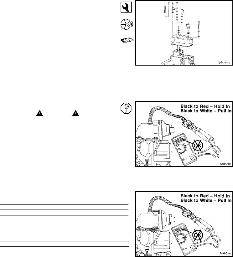
Solenoid Resistance Check
NOTE: Values are taken at 20C [68F] and rated voltage.
Minimum values are for 25-mm [1.00-in] maximum plunger
travel. As the temperature of the solenoid increases, the
voltage and resistance requirements increase, while the
amperage requirements decrease.
The solenoid resistance can be checked using a multimeter.
Disconnect the wiring harness, and check the solenoid
resistance.
coil canister.
Solenoid Voltage
Acceptable Resistance Range in Ohms
Pull-in
Hold-in
12
(0.198 to 0.242)
(10.00 to 12.21)
24
(0.738 to 0.902
(37.17 to 45.43)
Synchro-start solenoids with a 50.8-mm [2.00-in] diameter
coil canister.
Solenoid Voltage
Acceptable Resistance Range in Ohms
Pull-in
Hold-in
12
(0.175 to 0.213)
(12.75 to 15.56)
24
(0.554 to 0.678)
(46.76 to 57.15)
L-931