
TM 5-2420-230-24-2
B3.9 and B5.9 Series Engines
Fuel Lift Pump (005-045)
Section 5 - Fuel System - Group 05
Page 5-83
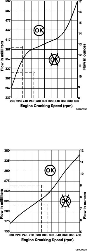
Use the chart in the illustration to find the correct flow
volume specification for Cummins Part No. 3930134,
3930135, 3932224, 3932225, 3933252, 3933253, 3936316,
3936317 fuel transfer pumps, and superseding Cummins
part numbers.
Draw a straight vertical line above the measured
cranking rpm
Draw a straight horizontal line from the measured
flow volume to the engine cranking rpm vertical line
to find the intersection point
Any intersection point above the required flow line
indicates an acceptable flow
Any intersection point below the required flow line
indicates unacceptable flow and a defective pump
or too much line restriction.
The maximum inlet restriction to the lift pump is 100
mm Hg [4 in Hg].
Use the chart in the illustration to find the correct flow
volume specification for Cummins Part No. 3930201,
3930202, 3932226, 3932227, 3933254, 3933255, 3936318,
3936319 fuel transfer pumps, and superseding Cummins
part numbers.
Draw a straight vertical line above the measured
cranking rpm
Draw a straight horizontal line from the measured
flow volume to the engine cranking rpm vertical line
to find the intersection point
Any intersection point above the required flow line
indicates an acceptable flow
Any intersection point below the required flow line
indicates unacceptable flow and a defective pump
or too much line restriction.
The maximum inlet restriction to the lift pump is 100
mm Hg [4 in Hg].
L-943