
TM 5-2420-230-24-2
B3.9 and B5.9 Series Engines
Engine Testing (Chassis Dynamometer) (014-002)
Section 14 - Engine Testing - Group 14
Page 14-7
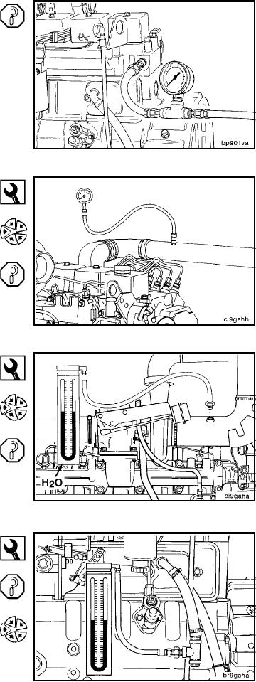
Measure the coolant pressure at a coolant tap on the ex-
haust side of the cylinder head.
Minimum Gauge Capacity:
415 kPa
[60 psi]
Pressure Gauge, Part No. ST-1273
Install a pressure gauge, Part No. ST-1273, in the location
shown.
Measure the intake manifold pressure (turbocharger boost).
Minimum Gauge Capacity:
1905 mm Hg
[75 in Hg]
Water Manometer, Part No. ST-1111-3
Vacuum Gauge, Part No. ST-434
Connect a water manometer, Part No. ST-1111-3, to the
turbocharger air inlet pipe to test air restriction.
NOTE: The manometer connection must be installed at a
90 degree angle to the airflow in a straight section of pipe,
one pipe diameter before the turbocharger, and be in be-
tween the turbocharger and the air filter.
NOTE: A vacuum gauge, Part No. ST-434, can be used in
place of the water manometer.
Minimum Gauge Capacity:
760 mm H2O
[30 in H2O]
Blowby Checking Tool, Part No. 3822476
Measure the blowby by installing blowby checking tool,
Part No. 3822476, in the crankcase breather vent. Connect
the blowby tool to a water manometer.
NOTE: Excessive blowby indicates a turbocharger mal-
function or an internal engine component malfunction, al-
lowing combustion gases to enter the crankcase.
Minimum Gauge Capacity:
1270 mm H2O
[50 in H2O]
L-1305