
TM 5-2420-232-10
0035
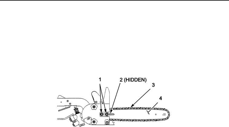
ADJUSTING CHAIN TENSION
0035
1.
Loosen the two bar flange nuts (Figure 5, Item 1).
2.
Turn the saw chain tension adjusting screw (Figure 5, Item 2) until the proper tension is achieved, as follows:
Pull the saw chain (Figure 5, Item 3) away from the bar (Figure 5, Item 4) using approximately 1 lb (4.4 N) of force. The
clearance between the chain and bar should be approximately 1/8 in.(3.2 mm).
3.
Hold the bar (Figure 5, Item 4) hose up and tighten the two bar flange nuts (Figure 5, Item 1) 150 lb-in (16.9 Nm).
4.
Check the chain tension again.
5.
Rotate the chain around the bar manually. If you hear a clicking noise, the chain drive links are hitting the bar. Repeat the
Adjusting Chain Tension procedure (Figure 5).
435-A1371
Figure 5. Adjusting Chain Tension
035
0035-7