
TM 5-2420-232-10
0049
SNOW PLOW SETUP
0049
1.
Attach snow plow to quick-hitch (WP 0004).
2.
Install crowd arm strut (WP0021 ).
3.
Install travel arm struts (WP 0021).
4.
Select loader/forklift suspension mode (WP 0004).
5.
Lower blade onto blocks until all weight is off the chains.
6.
Set the chains to approximately 19 links.
7.
Lift loader arms and remove blocks from under the blade.
8.
Lower loader arms onto travel struts.
9.
Ensure full length of the blade is in contact with ground and there is slack in both chains when blade is slewed to both the
left and the right.
10. If blade is not in contact with ground, repeat steps 4 thru 9 adjusting the chain ONE LINK AT A TIME until blade is in
contact with the ground.
SNOW PLOW ADJUSTMENT
0049
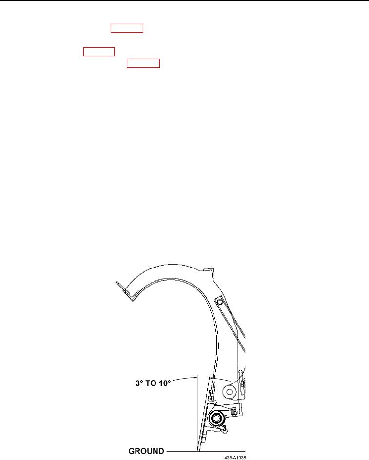
1.
The cutting edge attack angle should be 3 to 10 degrees from vertical when in the plowing position with all three struts
properly installed (Figure 1).
2.
Ensure the drive frame (Figure 2, Item 1) is in a horizontal position and the braces are mounted in the front holes
(Figure 2, Item 2) of the truss frame.
3.
If the braces are in the rear holes (Figure 2, Item 3), notify Field Maintenance to change the attack angle.
4.
Lower the plow until cutting edge is back down on the ground.
5.
Slew the plow a dozen times to ensure air is removed from the hydraulic system.
Figure 1. Mounting and Attack Angles
049
0049-2