
TM 5-3805-280-10
Maintenance
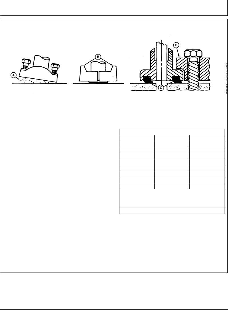
SERVICE RECOMMENDATIONS FOR METRIC SERIES FOUR BOLT FLANGE FITTING
A--Sealing Surface
B--Split Flange
C--Pinched O-Ring
D--Single Piece Flange
DO NOT use air wrenches. DO NOT tighten one
1. Clean sealing surfaces (A). Inspect. Scratches
cap screw fully before tightening the others. DO
cause leaks. Roughness causes seal wear.
NOT over tighten.
Out-of-flat causes seal extrusion. If defects cannot
be polished out, replace component.
a
TORQUE CHART
2. Install the correct O-ring (and backup washer if
b
Thread
Nm
lb-ft
required) into groove using petroleum jelly to hold it
M6
12
9
in place.
M8
30
22
M10
57
42
3. Split flange: Loosely assemble split flange (B)
M12
95
70
halves. Make sure split is centrally located and
M14
157
116
perpendicular to the port. Hand tighten cap screws
to hold parts in place. Do not pinch O-ring (C).
M16
217
160
M18
334
246
4. Single piece flange (D): Place hydraulic line in
M20
421
318
center of flange and install four cap screws. Flange
Tolerance 10%. The torques given are enough for the given
a
must be centrally located on port. Hand tighten cap
size connection with the recommended working pressure.
screws to hold flange in place. Do not pinch O-ring.
Increasing cap screw torque beyond these amounts will result in
flange and cap screw bending and connection failures.
5. After components are properly positioned and cap
b
Metric standard thread.
screws are hand tightened, tighten one cap screw,
then tighten the diagonally opposite cap screw.
Tighten two remaining cap screws. Tighten all cap
screws as specified in the chart below.
04T,90,K175
1905JAN961/1
20-28