
TM 5-3805-280-24-1
Sub-System Diagnostics
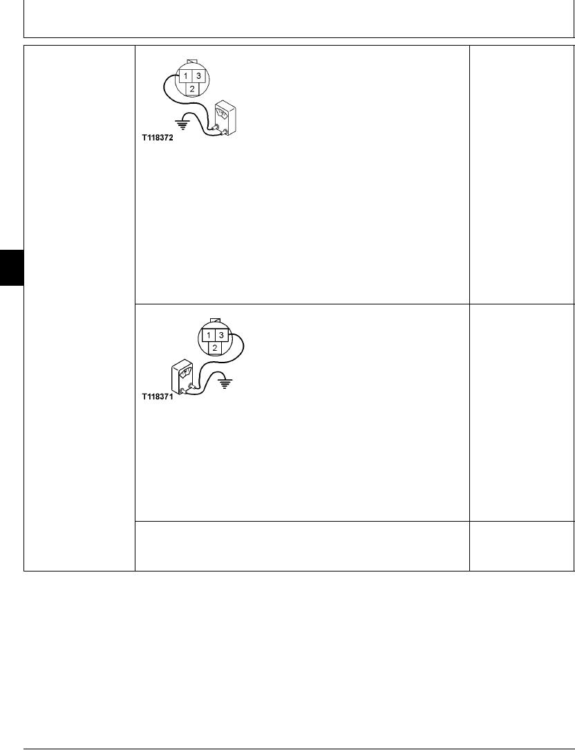
ARM IN PRESSURE
YES: Harness wire is OK.
SENSOR (B20)
Go to next step.
HARNESS CHECK
NO: Wire or engine and
pump controller has
failed. Repair.
T118372 UN21NOV98
1--Positive Terminal
2--Sense Terminal
3--Negative Terminal
Turn key switch OFF.
Disconnect harness from arm in pressure sensor.
Connect voltmeter to sensor harness connector pin 1 and ground.
9015
15
Turn key switch ON.
82
Does voltmeter read 5 volts?
YES: Harness wire is OK.
Go to next step.
NO: Wire has failed.
Repair.
T118371 UN21NOV98
1--Positive Terminal
2--Sense Terminal
3--Negative Terminal
Turn key switch OFF.
Connect ohmmeter to sensor harness connector pin 3 and ground.
Does ohmmeter read continuity?
1/2
4-147