
TM 5-3805-280-24-1
Sub-System Diagnostics
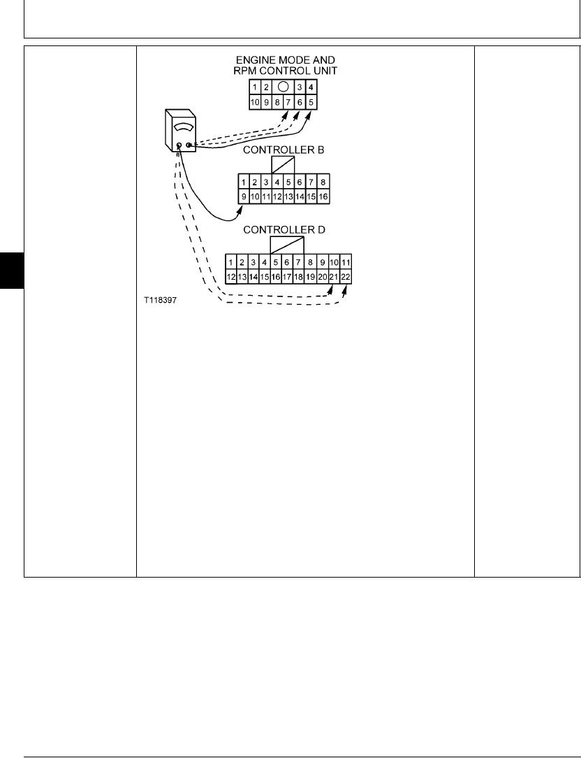
YES: Engine rpm dial
ENGINE RPM DIAL (R10)
harness is OK.
HARNESS CHECK
NO: Harness had failed.
Repair.
9015
15
80
T118397 1930NOV98
Disconnect 16-pin harness connector B and 22-pin harness connector D from engine
and pump controller.
Disconnect harness connector from engine mode and RPM control unit A4.
Measure continuity from pin 5 of engine mode and RPM control unit harness connector
to pin 9 of engine and pump controller harness connector B.
Measure continuity from pin 7 of engine mode and RPM control unit harness connector
to pin 22 of engine and pump controller harness connector D.
Measure continuity from pin 6 of engine mode and RPM control unit harness connector
to pin 21 of engine and pump controller harness connector D.
Is continuity measured?
1/1
4-145