
TM 5-3805-280-24-1
Sub-System Diagnostics
YES: Wire harness is OK.
Go to next check.
NO: Wire from connector
D to sensor harness
connector pin 2 has
failed. Repair.
9015
15
T118359 1921NOV98
85
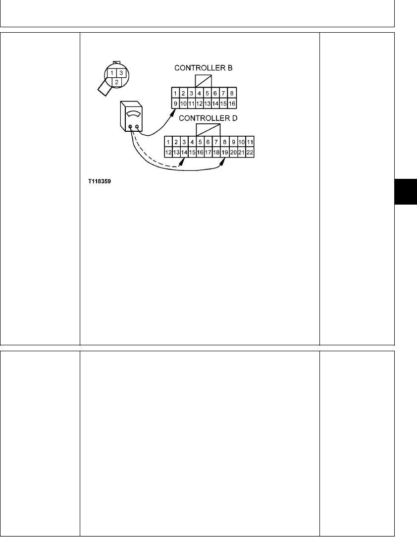
Install jumper between sensor harness connector pins 1 and 2.
Disconnect 22-pin connector D and 16-pin connector B from engine and pump
controller.
Measure continuity between pin 9 of harness connector B and pin 19 of harness
connector D (for front pressure sensor), or pin 14 of harness connector D (for rear
pressure sensor) .
Is continuity measured?
2/2
YES: Sensor is OK.
Install pump control test harness JT07353 in series with wiring harness and sensor.
REAR PUMP CONTROL
Engine and pump
PRESSURE SENSOR
controller may have
Connect voltmeter to test harness jacks.
(B21) AND FRONT
failed.
CONTROL PRESSURE
SENSOR (B22) CHECK
With engine running, pilot control lever forward, and hydraulic functions in neutral,
NO: Sensor has failed.
observe voltmeter.
Replace.
Is voltage 0.5 - 0.7 volts?
Slowly actuate boom up (for front pressure sensor B22) or left track (for rear pressure
sensor B21) until motion just begins.
Does voltage increase to 3.3 - 3.5 volts when pilot controller reaches full activation?
1/1
4-150