
TM 5-3805-280-24-1
Sub-System Diagnostics
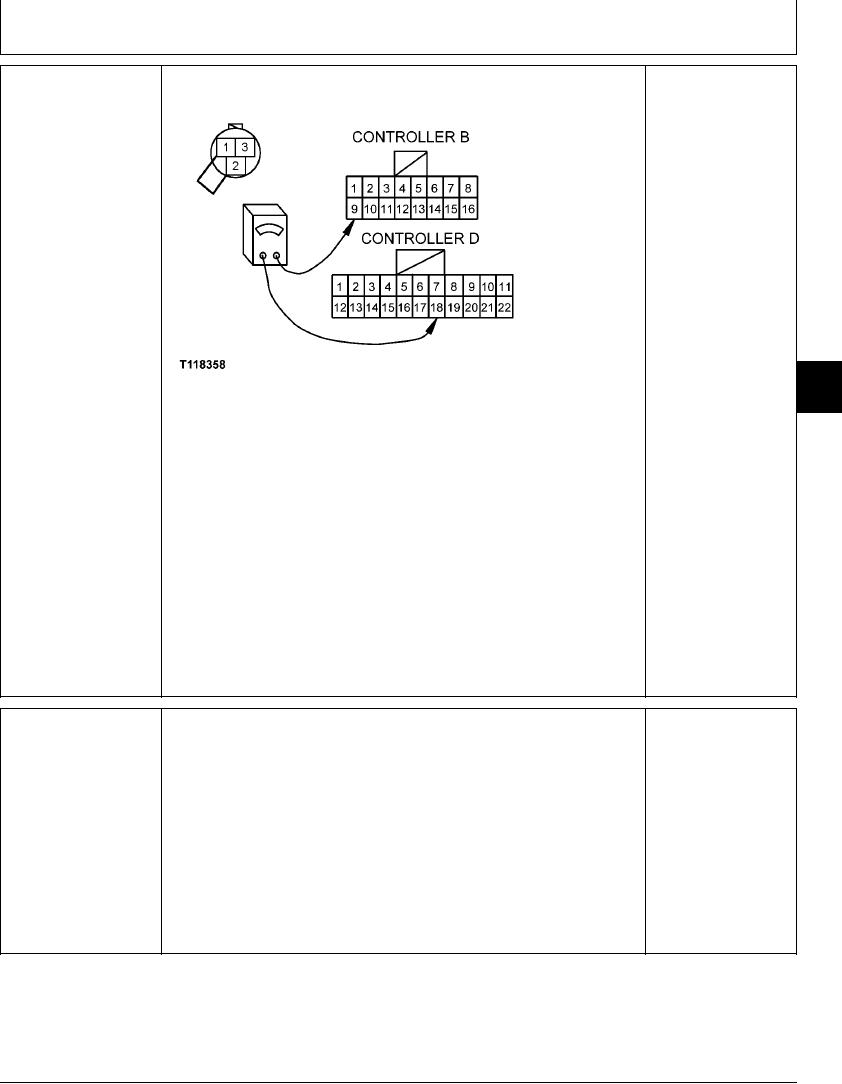
YES: Wire harness is OK.
Go to next check.
NO: Wire from pin 18 of
connector D to pin 2 of
sensor harness connector
has failed. Repair.
9015
15
T118358 1921NOV98
83
Install jumper between sensor harness connector pins 1 and 2.
Disconnect 22-pin connector D and 16-pin connector B from engine and pump
controller.
Measure continuity between pin 9 of harness connector B and pin 18 of harness
connector D.
Is continuity measured?
2/2
ARM IN PRESSURE
Install pump control test harness JT07353 in series with wiring harness and sensor.
YES: Sensor is OK.
SENSOR (B20) CHECK
Engine and pump
Connect voltmeter to test harness jacks.
controller may have
failed.
With engine running, pilot control lever forward, and hydraulic functions in neutral,
observe voltage.
NO: Sensor has failed.
Replace.
Is voltage between 0.5 and 0.7 volts?
Actuate arm in to achieve hydraulic function over relief.
Does voltage increase to between 3.3 and 3.5 volts with hydraulic function over relief?
1/1
4-148