
TM 5-3805-280-24-1
Tests
The engine and pump controller (EPC) is used to
switches (1--3, 5--7, and 14--16) are sent to the
control machine operation. Electronic input signals
controller.
from the engine rpm dial (4), sensors (9--13), and
TX,9025,GG2603 1921MAY982/2
JT05801 CLAMP-ON ELECTRONIC
TACHOMETER INSTALLATION
SERVICE EQUIPMENT AND TOOLS
JT05801 Clamp-On Electronic Tachometer
1. Before installing clamp-on electronic tachometer,
remove the paint from a straight section of injection
line within 100 mm (4 in.) of No. 1 injection nozzle.
Use emery cloth to remove the paint.
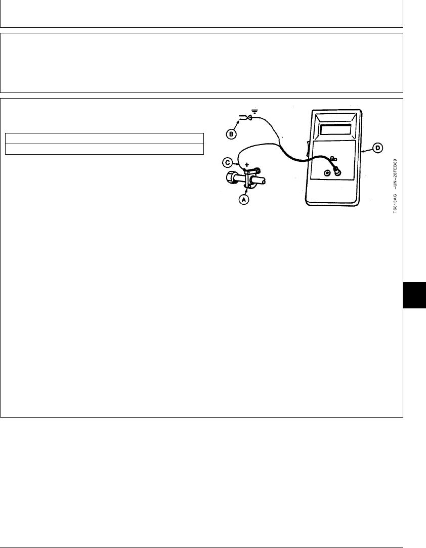
2. Install the clamp-on transducer (A). Tighten finger tight
only--DO NOT overtighten.
A--Clamp-On Transducer
B--Black Clip (-)
3. Connect the red clip (+) (C) to the clamp-on
C--Red Clip (+)
transducer.
D--Digital Readout Unit
4. Connect the black clip (-) (B) to a ground connection
such as the head of a cap screw or other metal part on
engine.
9025
25
29
5. Start the engine. Check for a reading on the digital
readout unit (D).
CED,TX08227,2879
1911NOV971/1
6-159