
TM 5-3805-280-24-1
C: The fan
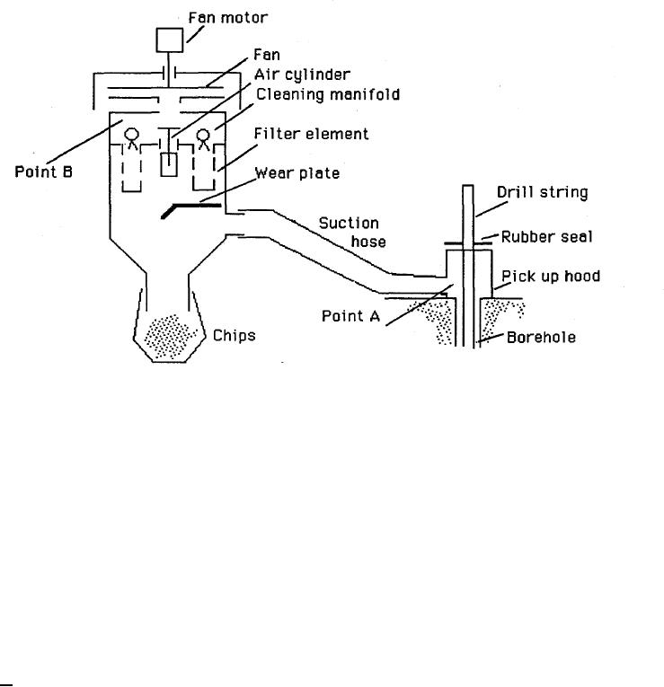
The dust collecting system:
The fan pumps out the air from. the clean side of the filters thus creating a vacuum at Point
B. During drilling air speed is higher at Point A than at Point B. The difference in speed
forces the air (in this case the flushing air) to move from Point A to Point B.
The air volume moved depends on the pressure difference and the flow resistance between
A and B.
As explained above it is necessary that the capacity of the dust collector is somewhat higher
than the volume of the flushing air coming out of the bore hole
Summing up:
1. The fan capacity and the flow resistance through the dust collector give the volume of
air that will pass through the dust collector.
2. This volume must be higher than the volume of the flushing air.
3. The air speed through the suction hose must be high enough (25 ni/sec +) to prevent
fallout.
4. The rig hydraulic system must be able to deliver sufficient oil volume (measured in
litters/minute) and oil pressure (in Bars) to run the fan motor at the required RPM's.
10-9