
TM 5-3805-280-24-1
Hydraulic System
4. Install ball (29).
6. Apply thread lock and sealer (medium strength) to
seat (30). Tighten seat.
5. Place ball on seat and tap ball with a hammer to
Brake Release Shuttle Valve Seat--Specification
obtain a tight fit between ball and seat. After
installing ball, but before tightening seat, insert a
02
Torque................................................................. 14.5 Nm (128 lb-in.)
metal bar into the plug hole so it rests on the ball.
0260
Tap other end of bar with a hammer to obtain a
28
7. Tighten plug.
tight fit between ball and housing.
Brake Release Shuttle Valve Plug--Specification
6. Apply thread lock and sealer (medium strength) to
seat (30). Using a 5 mm hex key wrench, tighten
Torque.................................................................... 34 Nm (301 lb-in.)
seat.
SERVO PISTON SHUTTLE VALVE
Servo Piston Shuttle Valve Seat--Specification
1. Remove servo piston shuttle valves (29--32).
Torque................................................................. 14.5 Nm (128 lb-in.)
2. Remove seat (30) using a 5 mm hex key wrench.
7. Tighten plug (31).
3. Seat may need to be heated to break down thread
Servo Piston Shuttle Valve Plug--Specification
lock and sealer. This can be done by inserting a
steel rod into the hole and heating the rod to
Torque.................................................................. 34 Nm (301 lb-in.)
transfer the heat to the seat.
IMPORTANT: Oil will leak past ball if it is not
seated properly.
TX,02,UU3724
1918SEP983/3
REMOVE AND INSTALL ROTARY MANIFOLD
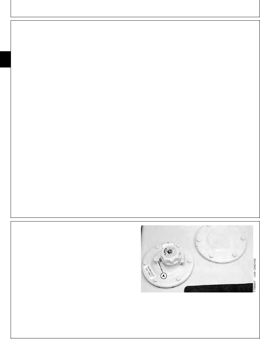
1. Loosen vent plug to relieve hydraulic oil tank pressure.
A--Vent Plug
Continued on next page
TX,02,VV2722 1918SEP981/7
12-51