
TM 5-3805-280-24-1
Hydraulic System
11. Remove lifting device. Install stop (D). Tighten cap
screws (C).
Stop-to-Frame Cap Screw--Specification
02
Torque ............................................................................. 40 Nm (30 lb-ft)
0260
34
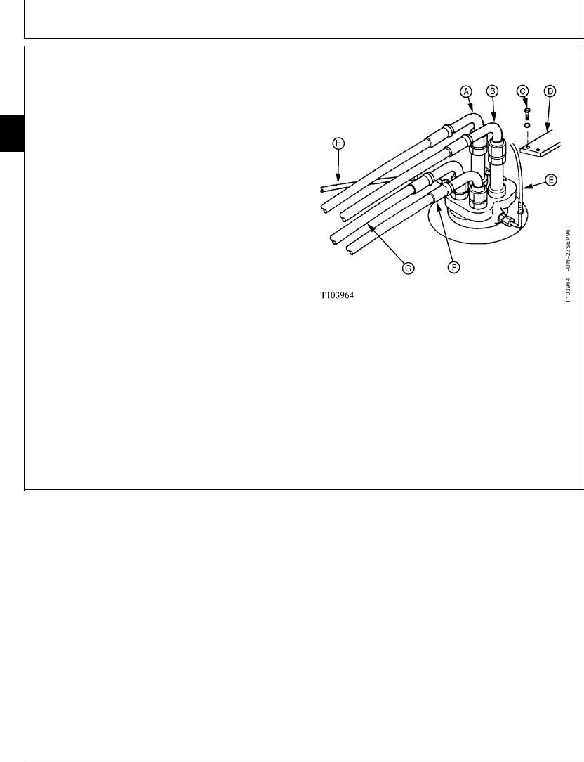
12. Connect lines (A, B, E--H). If ports on rotary manifold
do not align with lines, lower rotary manifold and do
the following steps.
A--Left Front Port To Left Propel Top Port
B--Right Front Port To Right Propel Top Port
C--Cap Screw
D--Stop
E--Right Side Port To Propel Speed Change
Solenoid Valve
F--Right Rear To Right Propel Bottom Port
G--Left Rear To Left Propel Bottom Port
H--Left Side Port To Return Manifold
Continued on next page
TX,02,VV2722 1918SEP986/7
12-56