
TM 5-3805-280-24-1
Hydraulic System
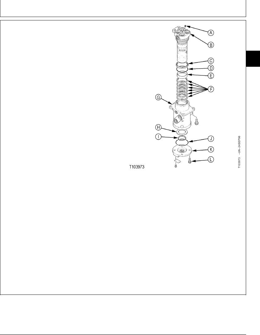
7. Inspect and repair as necessary. Keep hydraulic oil on
all disassembled parts.
8. Install bushing (E), O-ring (D), and seal (C) in housing
(G).
02
0260
9. Install oil seal rings (F) into housing (G)
37
IMPORTANT: Avoid damage to seals when installing
spindle into rotary manifold housing.
Clearance between spindle and housing
is approximately 0.1 mm (0.004 in.)
Spindle must not be tilted when
inserted into housing.
10. Carefully install spindle (B) into housing (G) so that
match marks align.
11. Install ring (H) with chamfered side down and snap
ring (I) with chamfered side down.)
12. Install O-ring (J) and cover (K) with cap screws (L).
Tighten cap screws.
Cover-to-Housing Cap Screw--Specification
Torque ............................................................................. 49 Nm (36 lb-ft)
A--Plug
B--Spindle
C--Dust Seal
D--O-Ring
E--Bushing
F--Oil Seal Ring (6 used)
G--Housing
H--Ring
I--Snap Ring
J--O-Ring
K--Cover
L--Cap Screw
TX,02,VV2723
1918SEP982/2
12-59