
TM 5-3805-280-24-1
Hydraulic System
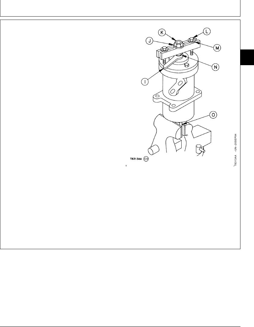
13. Install cap screws (O) in spindle. Clamp cap screws
in a vise.
14. Install cap screw (N), washer (J), and nut (K). Install
puller on rotary manifold using cap screws (L). Use
02
an extra thin service wrench (I) such as the
0260
D05242ST Service Wrench to hold cap screw (N).
35
15. Rotate manifold three times using nut (K) and a
torque wrench.
Rotary Manifold--Specification
Torque ..................................................... 373 Nm (275 lb-ft) first rotation
Torque ............................................................. 237 Nm (175 lb-ft) second
rotation
Torque .................................................... 170 Nm (125 lb-ft) third rotation
16. Raise rotary manifold into position against machine
mainframe. Tighten cap screws.
Manifold-to-Frame Cap Screw--Specification
Torque ............................................................................. 34 Nm (25 lb-ft)
17. Remove lifting device. Install stop. Tighten cap
screws (C).
Stop-to-Frame Cap Screw--Specification
I--Service Wrench
J--Washer
Torque ............................................................................. 40 Nm (30 lb-ft)
K--Nut
L--Cap Screw (2 used)
18. Connect lines.
M--Washer (2 used)
N--Cap Screw
O--Cap Screw (2 used)
TX,02,VV2722
1918SEP987/7
12-57