
TM 5-3805-280-24-2
Cylinder Head and Valves
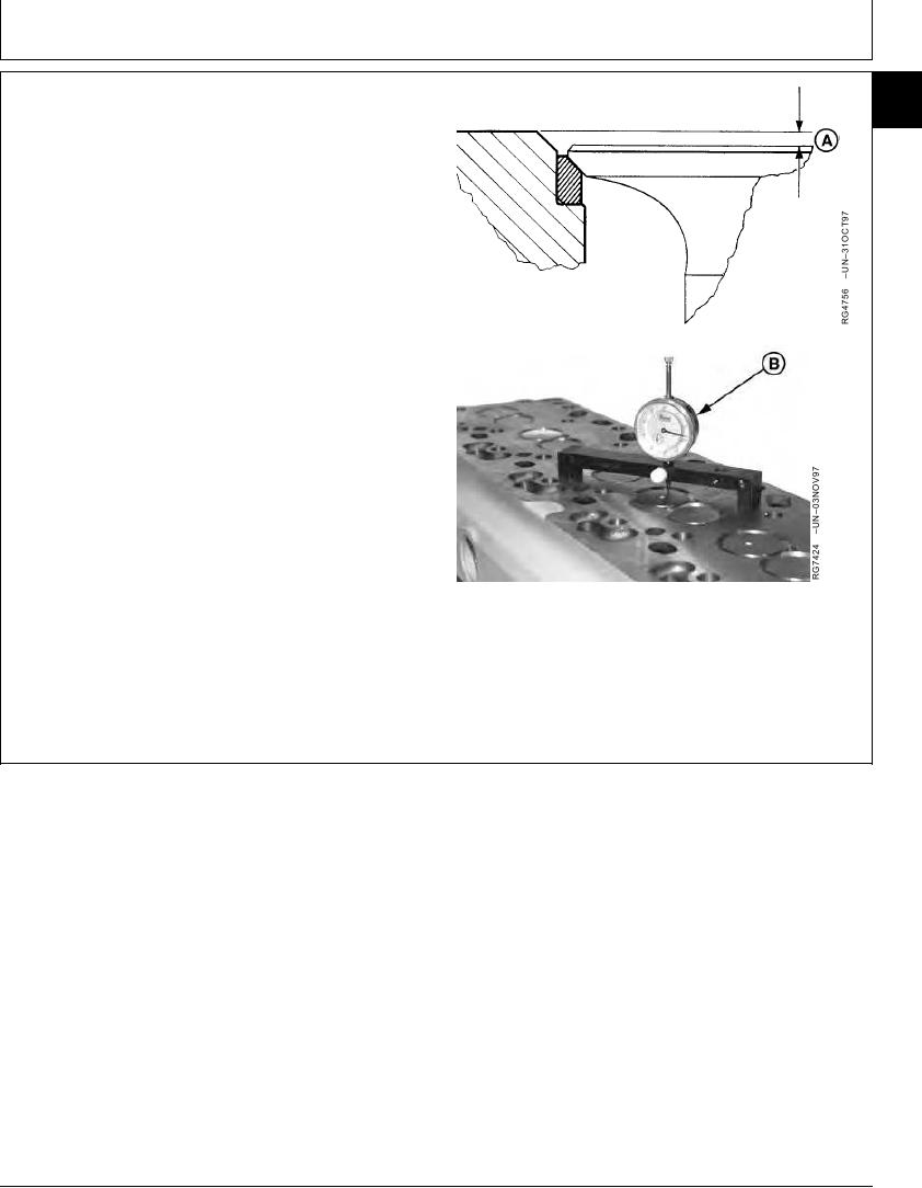
MEASURE VALVE RECESS IN CYLINDER
05
25
HEAD
Measure and record valve recess (A) using a depth
micrometer, magnetic base dial indicator or a dial indicator
with JDG451 Height Gauge (B). Measurements must be
made a maximum of 3.0 mm (0.12 in.) in from edge of
valve head.
Intake Valves--Specification
Recess in Cylinder Head .................... 0.61--1.11 mm (0.024--0.044 in.)
Worn Limit ................................................................. 1.63 mm (0.064 in.)
Exhaust Valve--Specification
Recess in Cylinder Head .................... 1.22--1.72 mm (0.048--0.068 in.)
Worn Limit .................................................................. 2.26 mm (0.089 in.)
Install new valves, inserts, or grind existing valves and
inserts, as necessary, to obtain proper valve recess. Grind
valve seat inserts as required. (See REMOVE VALVE
SEAT INSERTS later in this group.)
A--Valve Recess
B--Dial Indicator
RG,05,DT7368 1911NOV971/1
13-83