
TM 5-3805-280-24-2
Crankshaft, Main Bearings and Flywheel
REMOVE, INSPECT, AND INSTALL PISTON
15
47
COOLING ORIFICES
IMPORTANT: A piston cooling orifice failure could
cause damage to pistons, piston pins,
rod pin bushings and liners. If a piston
cooling orifice is left out, low or no oil
pressure will result.
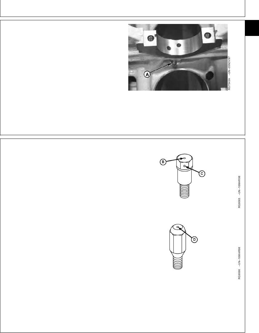
1. Remove and clean each piston cooling orifice (A) to
make sure it is not plugged or damaged. Replace if
questionable.
RG,15,DT7434 1914NOV971/2
NOTE: If equipped with early design orifice (B), add a
punch mark (C) to each orifice as shown. This is
not necessary on later design orifice (D) because
of its different shape. Adding a punch mark to
orifice (B) will also prevent cooling jets from being
mistakenly used on 300-Series Engines.
&pwrtec; Engines use a larger orifice diameter
cooling jet for proper lubrication and cooling of
piston skirts.
2. Install and tighten orifices.
Piston Cooling Orifice--Specification
Diameter ....................................................................... 1.4 mm (0.055 in.)
Piston Cooling Orifice--Specification
Torque ............................................................... 11 Nm (8 lb-ft) (96 lb-in.)
B--Early Design Orifice
C--Punch Mark
D--Later Design Orifice
RG,15,DT7434 1914NOV972/2
13-225