
TM 5-3805-280-24-2
Camshaft, Balancer Shafts and Timing Gear Train
REMOVE AND INSTALL CAMSHAFT
16
19
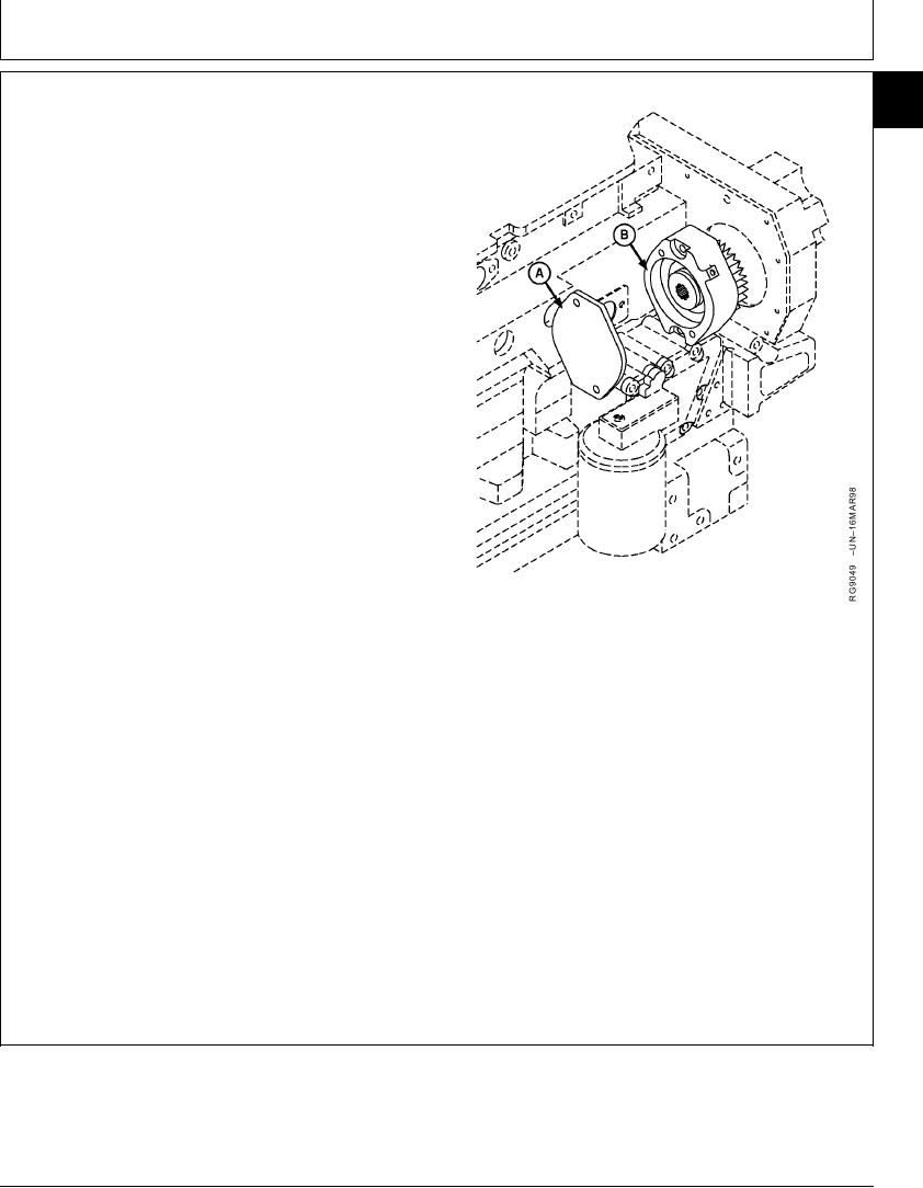
GEAR-DRIVEN AUXILIARY DRIVE
NOTE: Various auxiliary drive options are available;
removal and installation of all options are similar.
The auxiliary drive is integrated into the engine
front timing gear cover.
1. Remove lube line.
2. Remove auxiliary drive gear cover (A).
3. Clean and inspect cover for cracks or damage.
4. Remove auxiliary drive assembly (B).
NOTE: Auxiliary drive assembly is repairable. Refer to
CTM67 - OEM Accessories for additional service
information.
5. Inspect for cracked housing, worn or damaged
bearings, damaged gear or spline.
6. Repair or replace auxiliary drive assembly as needed.
7. Install gasket on auxiliary drive assembly and position
in the cylinder block plate. Install cap screws and
tighten to specifications.
A--Gear Cover
B--Auxiliary Drive Assembly
Auxiliary Drive-to-Cylinder Block Plate--Specification
Torque ............................................................................. 95 Nm (70 lb-ft)
8. Install cover and tighten cap screws or nuts to
specifications.
Auxiliary Drive Cover Plate--Specification
Torque ............................................................................. 55 Nm (41 lb-ft)
9. Install lube line.
RG,16,DT7504 1914NOV971/1
13-251